Supercharge Your Innovation With Domain-Expert AI Agents!

The wiring structure of the glue-injected package wire cap and the wiring process of the on-site glue-injected package wire cap

A technology of plastic injection packaging and wire caps, which is applied in the direction of cable connection/termination equipment, cable terminals, etc., can solve the problems of line insulation drop, wire joint corrosion, and complicated process, so as to reduce failures, prevent corrosion, The effect of simple process steps

Active Publication Date: 2016-08-31
CHINA 19TH METALLURGICAL CORP
View PDF8 Cites 0 Cited by
  • Summary
  • Abstract
  • Description
  • Claims
  • Application Information

AI Technical Summary

Problems solved by technology

However, after the wire cap is crimped and wired, because the end of the wire cap is open to the outside, in a humid environment, water will pass through the capillary phenomenon and immerse from the edge of the wire cap along the inner wall of the wire cap. When the water reaches the conductive part in the wire cap, it will be charged. The high potential end of the body conducts electricity through the water, causing the plastic shell of the wire cap to be charged
When the wire cap shell is in contact with the grounding body, the insulation of the line will drop, and when the human body touches the live wire cap, there will be a risk of electric shock
Therefore, this kind of wire cap wiring structure and wire cap wiring technology are not suitable for use in humid and explosive environments.
Especially when the wire connector is in a corrosive environment, corrosive liquid or gas will seep into the wire cap and cause corrosion to the wire connector
However, in the anti-corrosion terminal used in the prior art, the anti-corrosion process is implemented during manufacture; and the cost is high and the process is complicated

Method used


Image

  • The wiring structure of the glue-injected package wire cap and the wiring process of the on-site glue-injected package wire cap
  • The wiring structure of the glue-injected package wire cap and the wiring process of the on-site glue-injected package wire cap
  • The wiring structure of the glue-injected package wire cap and the wiring process of the on-site glue-injected package wire cap

Examples


Embodiment

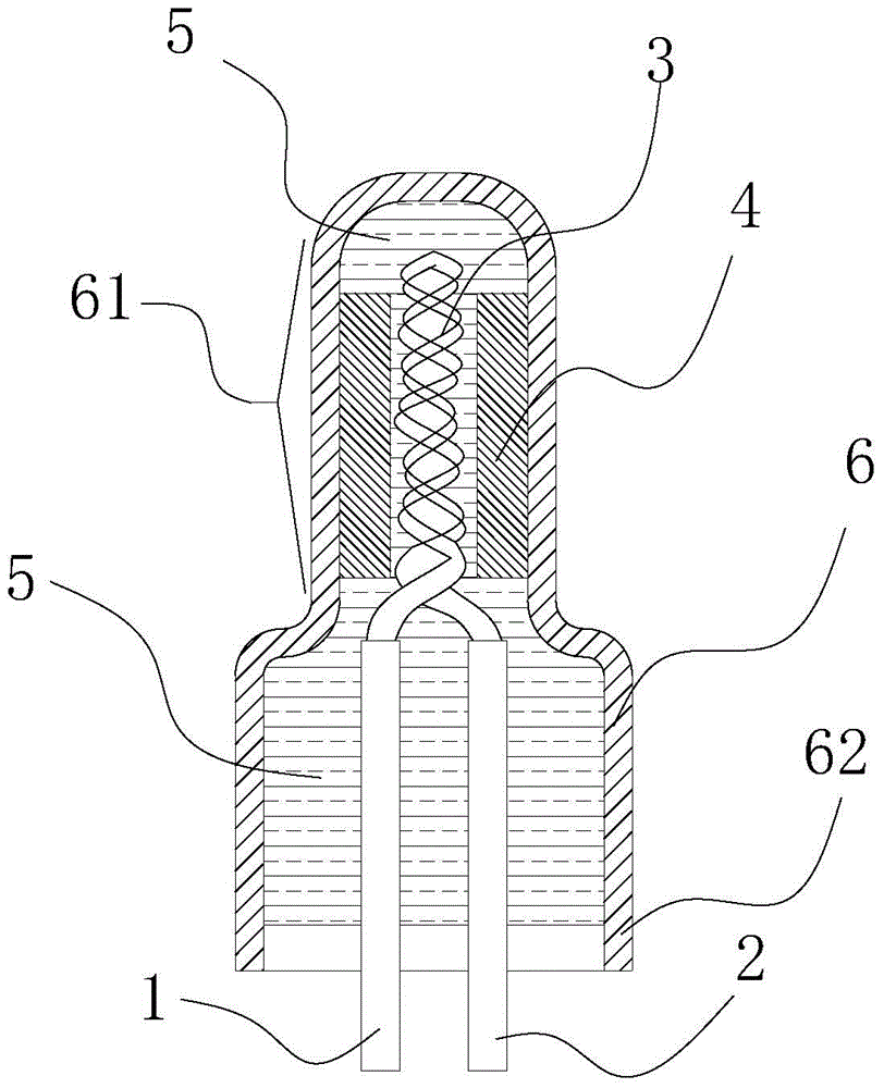
[0046] The wire cap 6 and the wire cap 6 made of PA66 have an insulation rating of ≥500V; the adaptable temperature is -40°C to 200°C, and the flame retardant grade is UL94-V0. Using the above-mentioned wire cap 6 to carry out on-site glue injection packaging wire cap wiring process includes the following steps:

[0047] A. First, peel off 13mm of the insulating sheath at the end of the A wire 1 that needs to be connected and the insulation sheath at the end of the B wire 2 that needs to be connected;

[0048] B. Put the wire core of the A wire 1 stripped of the insulation sheath and the wire core of the B wire 2 stripped of the insulation sheath together, so that they are twisted together to form a core wire 3; Inject the insulating sealing silica gel 5 into the wire cap 6 , until the insulating and sealing silica gel 5 fills the inner cavity between the inner crimping sleeve 4 of the wire cap 6 and the blind end section 61 of the wire cap 6, stop the glue injection;

[0049...


PUM


Abstract

The invention discloses a gel injection packaging line cap wiring structure and an on-site gel injection packaging line cap wiring technology, wherein the gel injection packaging line cap wiring structure can achieve corrosion protection and explosion protection of wire connectors. The wiring structure comprises a line cap, a wire A and a wire B. The technology includes the following steps that 1 an insulating sheath at one end of the wire A and an insulating sheath at one end of the wire B are stripped by 10-15 mm, wherein the wire A and the wire B need to be connected in an abutting mode; 2 wire cores of the wire A and the wire B are put together in a flush mode to be connected in a twisted mode so as to form a core wire, wherein insulating sheaths of the wire cores are stripped; 3 an inner cavity in the sealed end of the line cap is filled with insulation sealing silica gel; 4 the core wire penetrates into a crimping sleeve of the line cap, wherein the inserting depth of the core wire is larger than or equal to 95 percent of the length of the crimping sleeve; 5 the wire A and the wire B are separated from the root of a twisting joint portion of the core wire, and then insulation sealing silica gel is injected into the line cap; 6 the core wire and the crimping sleeve are pressed tightly. The wiring structure formed through the technology is used for connecting connectors of wires, and the connectors have good anti-corrosion property, waterproofness, anti-explosion performance and shock resistance.

Description

technical field [0001] The invention relates to a wire butt joint structure and technology, in particular to a wire cap wiring structure for glue injection encapsulation and a wire cap wiring technology for on-site glue injection encapsulation. Background technique [0002] It is known that wire cap wiring is a commonly used wire butt jointing process. It is often used for internal wiring of vibration equipment due to its advantages of easy operation, good contact, and shock resistance. However, after the wire cap is crimped and wired, because the end of the wire cap is open to the outside, in a humid environment, water will pass through the capillary phenomenon and immerse from the edge of the wire cap along the inner wall of the wire cap. When the water reaches the conductive part in the wire cap, it will be charged. The high potential end of the body conducts electricity through the water, causing the wire cap plastic casing to become charged. When the wire cap shell is ...

Claims


Application Information

Patent Timeline
Patent Type & Authority Patents(China)
IPC IPC(8): H02G1/14H02G15/04
Inventor 刘建川任兆兴兰厚今张世安赵红权
Owner CHINA 19TH METALLURGICAL CORP
Features
  • R&D
  • Intellectual Property
  • Life Sciences
  • Materials
  • Tech Scout
  • Unparalleled Data Quality
  • Higher Quality Content
  • 60% Fewer Hallucinations
Learn More