Different connection motor

A technology of separate and internal motors, which is applied in the direction of asynchronous induction motors, wind motor combinations, engines, etc., can solve the problems of difficult manufacturing and processing, large lateral force, and increased probability of bearing damage, so as to save power grid energy, Wide range of speed regulation and energy saving effect

Active Publication Date: 2014-08-13
WEIHAI DENGTONG PURIFICATION EQUIP
View PDF8 Cites 0 Cited by
  • Summary
  • Abstract
  • Description
  • Claims
  • Application Information

AI Technical Summary

Problems solved by technology

[0007] At present, the generator sets that realize variable speed and constant frequency operation mainly include double-fed asynchronous generator sets, especially widely used in megawatt-level wind power systems. Double-fed asynchronous generator sets are equipped with gearboxes with high speed-up ratios as transmission components. A full-power frequency converter, the gearbox is large in size and weight, which increases the complexity and cost of the wind power generation system, and the maintenance cost is high
The sequential connection between the main shaft of the impeller of the wind power generation system and the input shaft of the gearbox, coupling, and doubly-fed asynchronous generator set requires accurate alignment, otherwise it will cause vibration, the bearing will be subjected to a large lateral force, and the probability of bearing damage greatly increase
For example, the engineering cost of replacing a 1.5MW gearbox is 800,000 yuan, and the unit price of the gearbox is 1.2 million yuan, so the various costs of the gearbox are very high
With the increasing capacity of wind turbines, gearboxes and doubly-fed asynchronous generators are also increasing, and manufacturing and processing are becoming more and more difficult, and machining accuracy is difficult to guarantee, and the cost is getting higher and higher.

Method used


Image

  • Different connection motor
  • Different connection motor
  • Different connection motor

Examples


no. 1 example

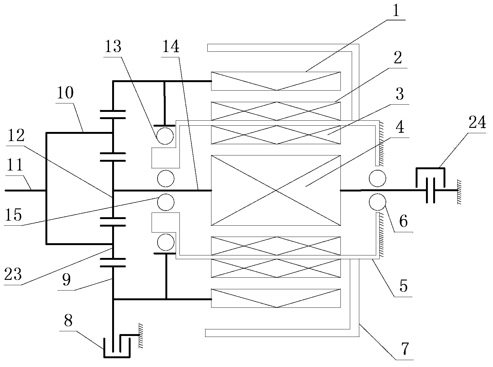
[0023] Such as Figure 1A The shown differential motor is used as a motor, and it includes an inner motor and an outer motor, the inner motor includes an inner motor rotor 4 and an inner motor stator 3, and the outer motor includes an outer motor rotor 1 and an outer motor stator 2. The inner motor rotor 4 is installed in the inner and outer stator frame 5, the inner motor rotor 4 is provided with a rotating shaft 14, and the rotating shaft 14 protrudes from both ends of the inner and outer stator frame 5 and is supported on the inner and outer stator frame 5 through the rear support bearing 6 and the front support bearing 15 . The inner motor stator 3 is installed on the inner wall of the inner and outer stator frames 5 . The outer motor is an outer rotor motor, the outer motor stator 2 is installed on the outer wall of the inner and outer stator frames 5, the outer motor rotor 1 is supported on the inner and outer stator frames 5 through support bearings 13, and the support ...

no. 2 example

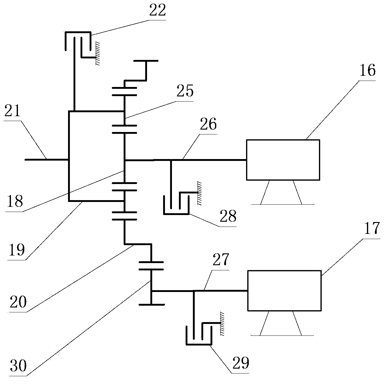
[0045] Refer below Figure 1B , the multi-connected motor is used as a motor, which includes an upper motor 16, a lower motor 17, and a planetary gear mechanism. The planetary gear mechanism includes a sun gear 18, a planetary carrier 19, a planetary gear 25, and a double ring gear 20. The upper motor The rotating shaft 26 of 16 is connected with the sun gear 18, and the output shaft 21 is fixedly connected with the planet carrier 19. The rotating shaft 27 of the lower motor 17 is connected with the duplex ring gear 20 through a gear 30 . Upper clutch 28, lower clutch 29 are used to fix the rotating shaft of upper motor 16, lower motor 17 respectively.

[0046] The upper motor 16 and the lower motor 17 are vertically arranged in a vertical manner, which is different from the concentric arrangement in the first embodiment. They can be set up in such a way that one of them is a motor working at power frequency as the main motor, and the other is a variable frequency motor cont...

no. 3 example

[0052] Before describing this embodiment, it needs to be explained as follows. In a wind power generation system, since the wind energy is proportional to the cube of the wind speed, when the wind speed changes within a certain range, if the windmill is allowed to move at variable speeds, the purpose of better utilization of wind energy can be achieved. . For a large-scale wind power generation system, under the rated wind speed condition of level 7 wind, the generator can run at full load and achieve the highest efficiency, and the working condition of the wind below level 5 cannot reach full load operation and cannot reach the highest efficiency.

[0053] Such as Figure 1A The shown variable-connection motor is used as a generator and is applied in a wind power generation system, and both the inner motor and the outer motor are generators. The difference between the structure of this embodiment and the first embodiment is that the frequency converter can only be connected t...


PUM


Abstract

The invention relates to a different connection motor, for solving the technical problems of large size, heavy weight, large mechanical loss and rotation difference, quite low efficiency, unstable speed control, low power factor, poor speed regulation precision and high maintenance cost of a conventional fluid coupling device. The different connection motor comprises a primary motor working under power frequency and a secondary motor working under variable frequency. A planetary gear mechanism is connected between the primary motor and the secondary motor, the planetary gear mechanism is provided with a planet carrier, and the planet carrier is fixedly connected with an output shaft. The different connection motor can be used for motor driving or wind power generation.

Description

technical field [0001] The invention relates to a motor, in particular to a different-connected motor in which a power-frequency motor and a variable-frequency motor are connected together by a planetary gear mechanism. Background technique [0002] The hydraulic coupling is a non-rigid coupling with liquid as the working medium. When the input speed is constant, the output speed and torque are changed by changing the fullness of the working chamber (usually adjusted by a catheter). Hydraulic couplings are widely used in high-power fans and transportation machinery. [0003] The output shaft of the motor is connected with the input shaft of the hydraulic coupling, and the output shaft of the hydraulic coupling is connected with the driven load. When in use, the motor starts with no load first, and then the current and torque change from small to large. The output shaft of the hydraulic coupler drives the high-power fan to start gradually and enters the working condition, wh...

Claims


Application Information

Patent Timeline
Patent Type & Authority Applications(China)
IPC IPC(8): H02K7/20H02K7/10
CPCH02K16/00H02K7/10H02K7/20H02K7/102H02K17/12H02K7/116F03D9/00
Inventor 胡云龙
Owner WEIHAI DENGTONG PURIFICATION EQUIP
Why Eureka
Try Eureka