Different motor
A technology of different coupling and main motor, which is applied in the direction of asynchronous induction motors, electrical components, electromechanical devices, etc., can solve the problems of difficult manufacturing and processing, large lateral force, high maintenance costs, etc., and achieve power grid energy saving and speed regulation range Wide, easy-to-maintain effect
- Summary
- Abstract
- Description
- Claims
- Application Information
AI Technical Summary
Problems solved by technology
Method used
Image
Examples
no. 1 example
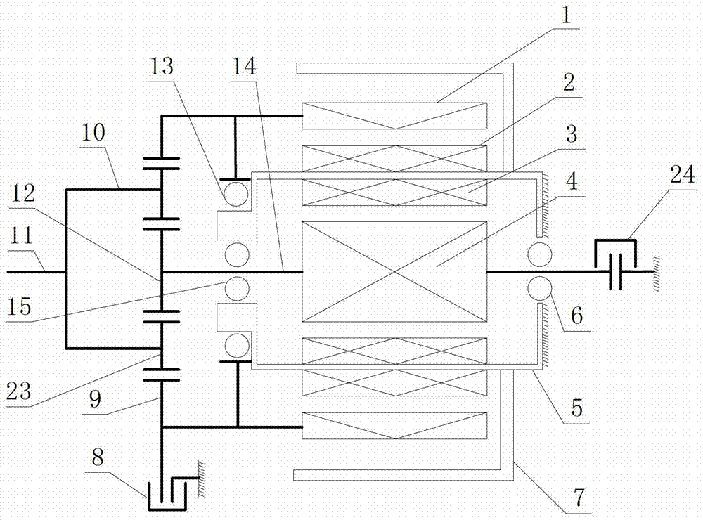
[0023] Such as Figure 1A The shown differential motor is used as a motor, and it includes an inner motor and an outer motor, the inner motor includes an inner motor rotor 4 and an inner motor stator 3, and the outer motor includes an outer motor rotor 1 and an outer motor stator 2. The inner motor rotor 4 is installed in the inner and outer stator frame 5, the inner motor rotor 4 is provided with a rotating shaft 14, and the rotating shaft 14 protrudes from both ends of the inner and outer stator frame 5 and is supported on the inner and outer stator frame 5 through the rear support bearing 6 and the front support bearing 15 . The inner motor stator 3 is installed on the inner wall of the inner and outer stator frames 5 . The outer motor is an outer rotor motor, the outer motor stator 2 is installed on the outer wall of the inner and outer stator frames 5, the outer motor rotor 1 is supported on the inner and outer stator frames 5 through support bearings 13, and the support ...
no. 2 example
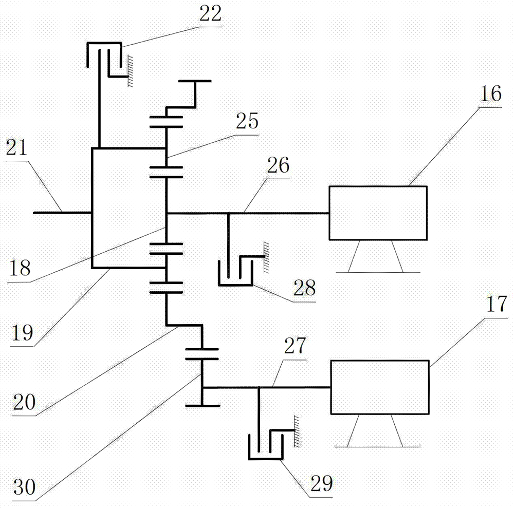
[0045] Refer below Figure 1B , the multi-connected motor is used as a motor, which includes an upper motor 16, a lower motor 17, and a planetary gear mechanism. The planetary gear mechanism includes a sun gear 18, a planetary carrier 19, a planetary gear 25, and a double ring gear 20. The upper motor The rotating shaft 26 of 16 is connected with the sun gear 18, and the output shaft 21 is fixedly connected with the planet carrier 19. The rotating shaft 27 of the lower motor 17 is connected with the duplex ring gear 20 through a gear 30 . Upper clutch 28, lower clutch 29 are used to fix the rotating shaft of upper motor 16, lower motor 17 respectively.
[0046] The upper motor 16 and the lower motor 17 are vertically arranged in a vertical manner, which is different from the concentric arrangement in the first embodiment. They can be set up in such a way that one of them is a motor working at power frequency as the main motor, and the other is a variable frequency motor cont...
no. 3 example
[0052] Before describing this embodiment, it needs to be explained as follows. In a wind power generation system, since the wind energy is proportional to the cube of the wind speed, when the wind speed changes within a certain range, if the windmill is allowed to move at variable speeds, the purpose of better utilization of wind energy can be achieved. . For a large-scale wind power generation system, under the rated wind speed condition of level 7 wind, the generator can run at full load and achieve the highest efficiency, and the working condition of the wind below level 5 cannot reach full load operation and cannot reach the highest efficiency.
[0053] Such as Figure 1A The shown variable-connection motor is used as a generator and is applied in a wind power generation system, and both the inner motor and the outer motor are generators. The difference between the structure of this embodiment and the first embodiment is that the frequency converter can only be connected t...
PUM
 Abstract
Description
Claims
Application Information
 - R&D
- Intellectual Property
- Life Sciences
- Materials
- Tech Scout
- Unparalleled Data Quality
- Higher Quality Content
- 60% Fewer Hallucinations
Browse by: Latest US Patents, China's latest patents, Technical Efficacy Thesaurus, Application Domain, Technology Topic, Popular Technical Reports.
© 2025 PatSnap. All rights reserved.Legal|Privacy policy|Modern Slavery Act Transparency Statement|Sitemap|About US| Contact US: help@patsnap.com


