Supercharge Your Innovation With Domain-Expert AI Agents!

Zigzag wiring type alternating-current voltage adjustment device

A technology of AC voltage regulation and line type, applied in the direction of conversion equipment that can be converted to DC without intermediate conversion, it can solve the problems of limited range of voltage regulation, unable to meet the needs of urban construction and development, etc., and achieve simple regulation circuit and low loss Small, the effect of power factor improvement

Active Publication Date: 2014-08-13
STATE GRID CORP OF CHINA +1
View PDF6 Cites 0 Cited by
  • Summary
  • Abstract
  • Description
  • Claims
  • Application Information

AI Technical Summary

Problems solved by technology

[0003] In order to solve the problem that the existing voltage regulating device has a limited voltage regulating range and cannot meet the needs of urban construction and development, the present invention provides a zigzag wiring type AC voltage regulating device

Method used


Image

  • Zigzag wiring type alternating-current voltage adjustment device
  • Zigzag wiring type alternating-current voltage adjustment device
  • Zigzag wiring type alternating-current voltage adjustment device

Examples


Embodiment 1

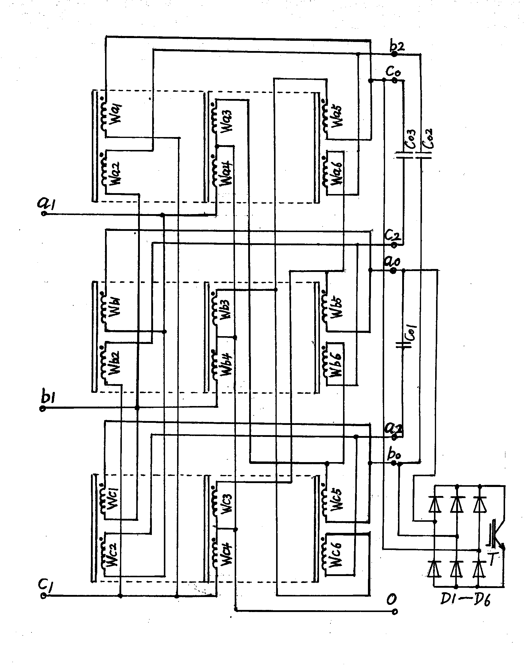
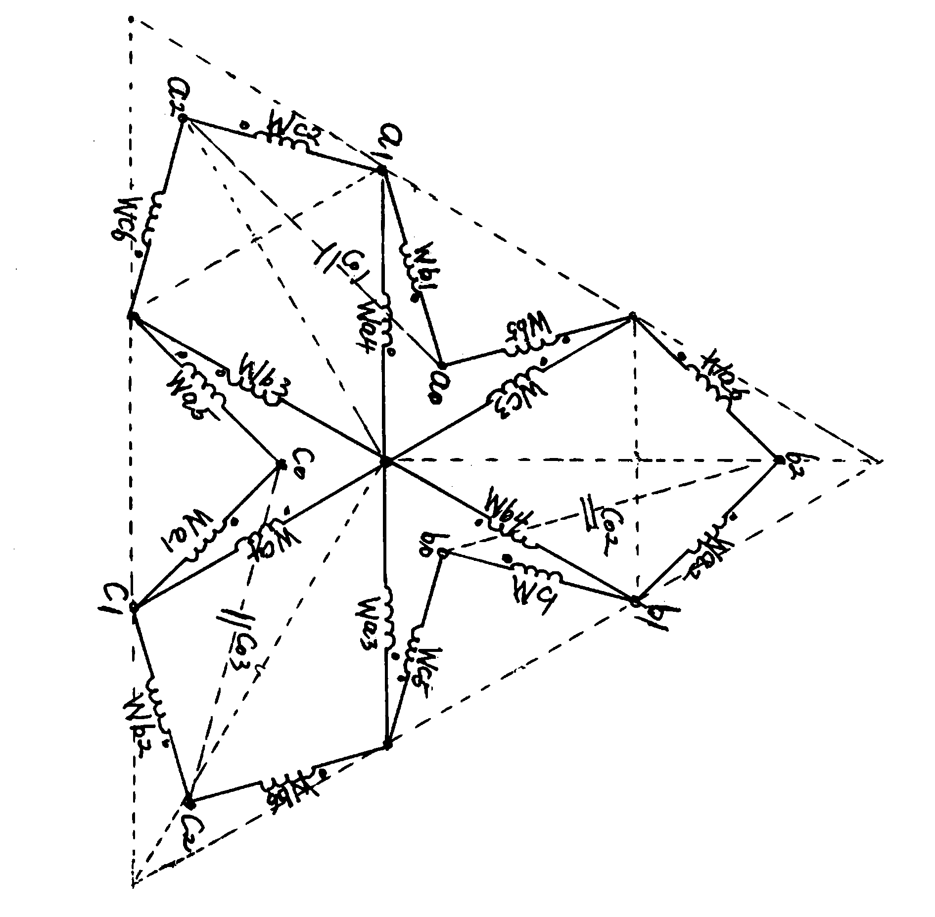
[0022] Embodiment 1: A zigzag connection type AC voltage regulating device, including a-phase iron core, b-phase iron core and c-phase iron core with a three-column structure respectively having a left column, a central column and a right column, and a central column of the a-phase iron core Winding Wa4 is wound on it, the head end of winding Wa4 is connected to the tail end of winding Wa3, winding Wb4 is wound on the center column of phase b core, the head end of winding Wb4 is connected to the tail end of winding Wb3, and the center column of phase c core A winding Wc4 is wound on it, the head end of the winding Wc4 is connected to the tail end of the winding Wc3, and the tail end of the winding Wa4, the tail end of the winding Wb4 and the tail end of the winding Wc4 are the input ends of phase a, phase b and phase c respectively, The head end of the winding Wa4, the head end of the winding Wb4 and the head end of the winding Wc4 are connected to each other and the connection...

Embodiment 2

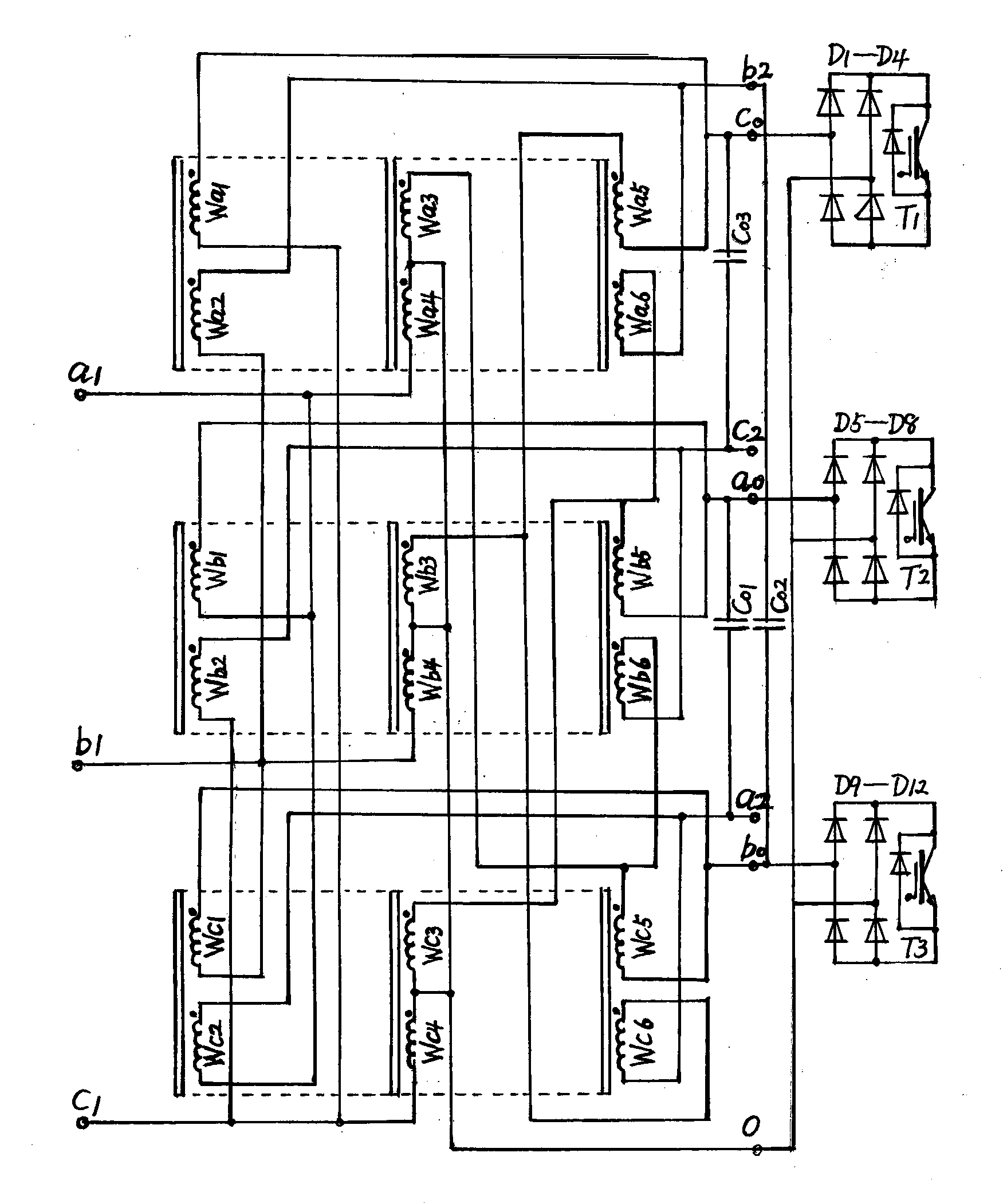
[0028] Embodiment 2: A zigzag connection type AC voltage regulating device, including a-phase iron core, b-phase iron core and c-phase iron core with a three-column structure respectively having a left column, a central column and a right column, and a central column of a-phase iron core Winding Wa4 is wound on it, the head end of winding Wa4 is connected to the tail end of winding Wa3, winding Wb4 is wound on the center column of phase b core, the head end of winding Wb4 is connected to the tail end of winding Wb3, and the center column of phase c core A winding Wc4 is wound on it, the head end of the winding Wc4 is connected to the tail end of the winding Wc3, and the tail end of the winding Wa4, the tail end of the winding Wb4 and the tail end of the winding Wc4 are the input ends of phase a, phase b and phase c respectively, The head end of the winding Wa4, the head end of the winding Wb4 and the head end of the winding Wc4 are connected to each other and the connection is ...


PUM


Abstract

The invention relates to the field of alternating-current stabilized power sources and transformers, in particular to a zigzag wiring type alternating-current voltage adjustment device. The zigzag wiring type alternating-current voltage adjustment device comprises a phase-a iron core, a phase-b iron core and a phase-b iron core, wherein the phase-a iron core, the phase-b iron core and the phase-b iron core are respectively provided with a three-column-type structure composed of a left side column, a center column and a right side column. The left side columns, the center columns and the right side columns of the phase-a iron core, the phase-b iron core and the phase-c iron core are wound by windings. The output end of the voltage adjustment device is connected with a rectifier bridge. The direct-current end of the rectifier bridge is connected with an electronic component capable of being switched off. According to the zigzag wiring type alternating-current voltage adjustment device, the three-phase iron cores of the three-column-type structures and the eighteen windings are used, three capacitors are used for forming a PWM voltage adjusting main circuit, and the voltage adjusting device has the advantages that the wide range for adjusting the nominal voltage is from -50% to 15%, meanwhile, the response time is shorter than 30 ms, the loss is smaller than 1%, the power factor is improved by 0.1 on average, and the cost is low.

Description

technical field [0001] The invention relates to the field of an AC stable power supply and a transformer, in particular to a zigzag wiring type AC voltage regulating device. Background technique [0002] The current transformer on-load voltage regulation and high-power AC voltage regulation technology is limited to the adjustment range of no more than plus or minus 20% of the rated voltage. If the adjustment range is further expanded, especially the negative adjustment range exceeds 30% of the rated voltage. However, there are certain problems in the current pressure regulation technology. The current high-power compensating AC voltage regulator uses two electromagnetic devices, the compensating transformer and the self-coupling voltage regulator, and the drive of the servo motor to adjust the output voltage, but it uses two sets of electromagnetic devices for adjustment and compensation. There is a problem of slow response and low efficiency. The pulse transformer-coupled...

Claims


Application Information

Patent Timeline
IPC IPC(8): H02M5/10
Inventor 刘涛张保平
Owner STATE GRID CORP OF CHINA
Features
  • R&D
  • Intellectual Property
  • Life Sciences
  • Materials
  • Tech Scout
  • Unparalleled Data Quality
  • Higher Quality Content
  • 60% Fewer Hallucinations
Learn More