Spectrum sensing method based on non-refactoring framework

A spectrum sensing and framework technology, applied in the field of spectrum sensing based on a non-reconfiguration framework, which can solve the problems of complex algorithms, inability to sense spectrum, and low utilization of spectrum resources.

Inactive Publication Date: 2014-08-13
HARBIN INST OF TECH
View PDF2 Cites 5 Cited by
  • Summary
  • Abstract
  • Description
  • Claims
  • Application Information

AI Technical Summary

Problems solved by technology

[0010] The present invention aims to solve the problems of low utilization rate of spectrum resources in wireless communication technology, complex traditional compressed sensing spectrum sensing algorithm, and the inability to directly use compressed sampling data matrix for spectrum sensing under a non-reconfiguration framework

Method used


Image

  • Spectrum sensing method based on non-refactoring framework
  • Spectrum sensing method based on non-refactoring framework
  • Spectrum sensing method based on non-refactoring framework

Examples


specific Embodiment approach 1

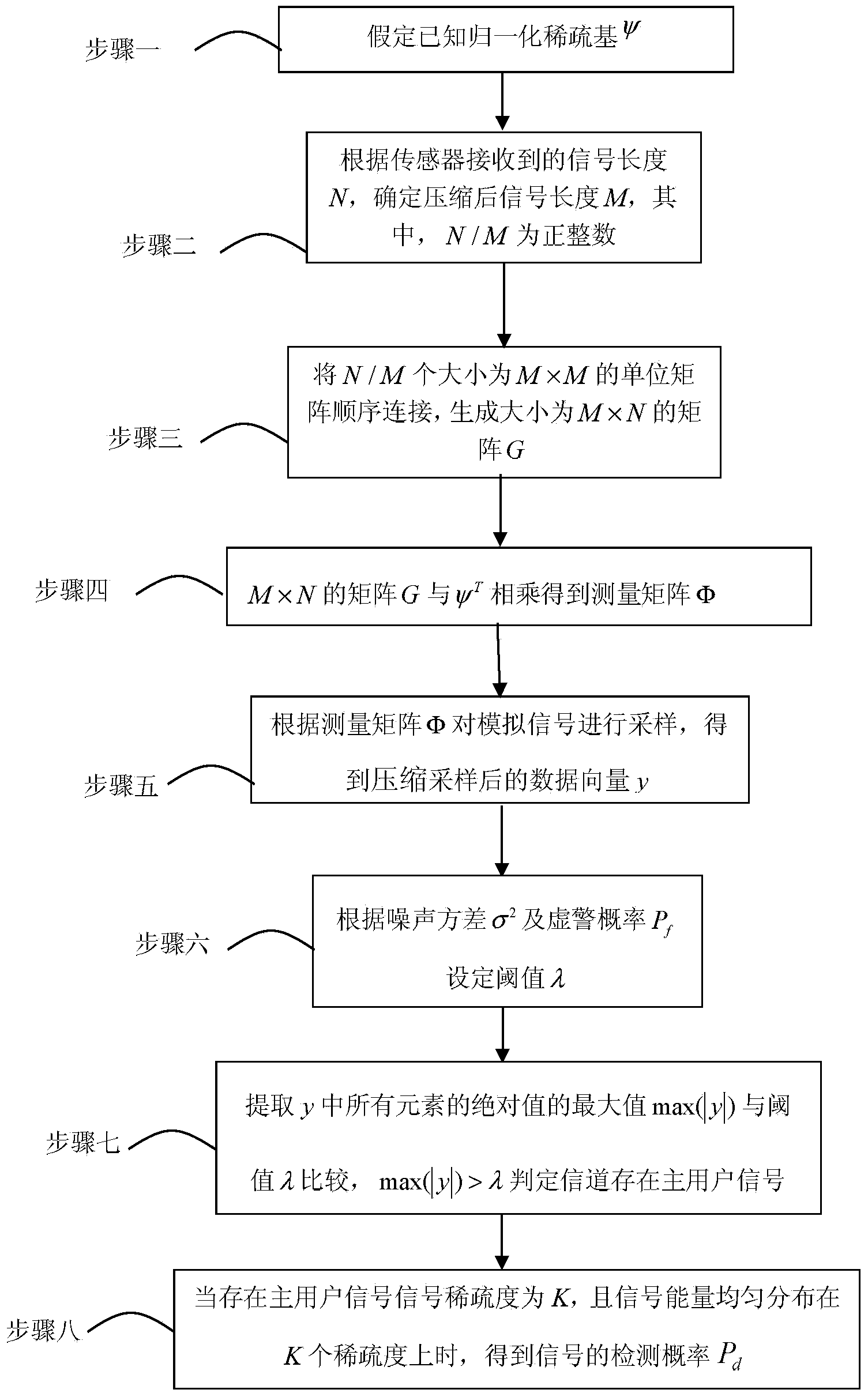
[0030] Specific implementation mode 1: A spectrum sensing method based on a non-reconfiguration framework in this implementation mode is specifically prepared according to the following steps:

[0031] Step 1. Assume that the normalized sparse basis ψ is known;

[0032] Step 2. Determine the compressed signal length M according to the row number N of ψ, wherein N / M is a positive integer;

[0033] Step 3, sequentially connecting N / M identity matrices with a size of M×M to generate a matrix G with a size of M×N;

[0034] Step 4, M×N matrix G and ψ T Multiply to get the measurement matrix Φ;

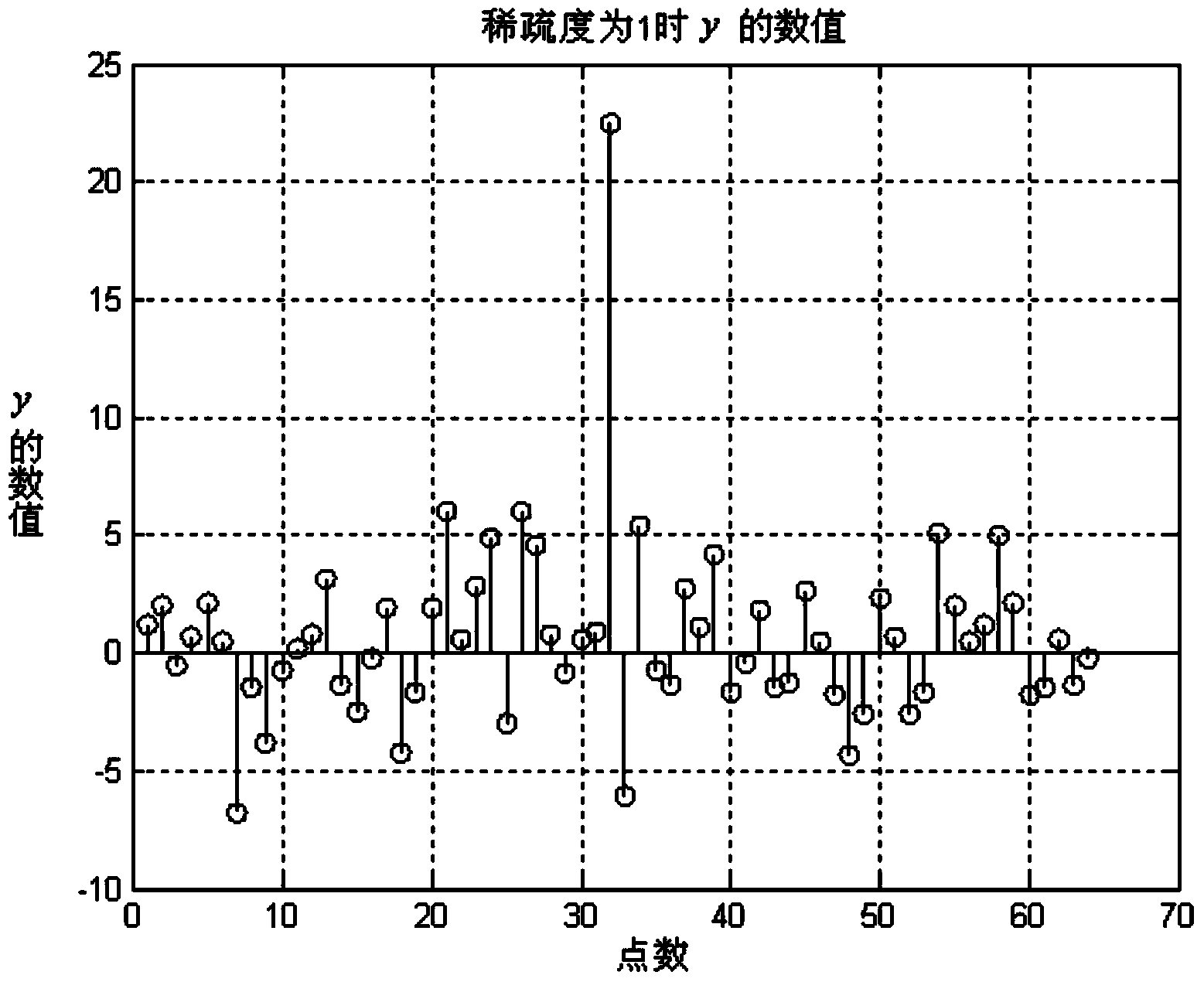
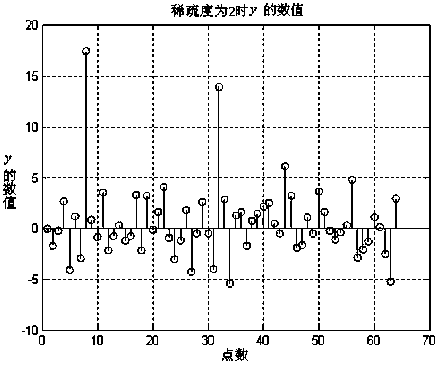
[0035] Step 5: Sampling the signal according to the measurement matrix Φ to obtain the compressed and sampled data vector y;

[0036] Step 6. According to the noise variance σ 2 and false alarm probability P f Set the threshold λ;

[0037] Step 7: Extract the maximum value max(|y|) of the absolute values ​​of all elements in y and compare it with the threshold λ, max(|y|)>λ determines...

specific Embodiment approach 2

[0043] Specific embodiment 2: The difference between this embodiment and specific embodiment 1 is that in step 3, N / M unit matrices with a size of M×M are sequentially connected to generate a matrix G with a size of M×N as an M×N matrix , N is the length of the signal x, which is formed by connecting N / M M×M unit matrices, and the specific form is shown in formula (4):

[0044] (4). Other steps and parameters are the same as those in Embodiment 1.

specific Embodiment approach 3

[0045] Specific embodiment three: the difference between this embodiment and specific embodiment one or two is: the matrix G and ψ of M×N in step four T The specific process of multiplying to get the measurement matrix Φ is:

[0046] Assuming that the signal x itself is not sparse, the signal x is represented by a sparse vector s under the orthogonal sparse transformation, which is recorded as x=ψs, where the sparsity of s is K (only K non-zero elements), and ψ is the normalization of N×N Sparse basis; the signal after compressed sampling is

[0047] x ‾ = Φx - - - ( 1 )

[0048] Rewrite (1) as:

[0049] x ‾ = Φψs - - - ( 2 )

[0050] in, It is a vector of M rows and 1 column, that is, the...


PUM


Abstract

The invention relates to a spectrum sensing method based on a non-refactoring framework and aims at solving the problems that the utilization ratio of a spectrum resource authorized by a wireless communication technology is low, a conventional compressed sensing spectrum sensing algorithm is complex, and spectrum sensing can not be carried out by directly utilizing a data matrix which is in compressed sampling under the non-refactoring framework. The spectrum sensing method comprises the steps of 1, determining normalized sparse-group psi; 2, according to the signal length N, determining the signal length M after compressing; 3, generating an M*N matrix G; 4, multiplying the M*N matrix G and psi<T> to obtain a measuring matrix phi; 5, obtaining a data vector y after compressed sampling; 6, setting a threshold value lambda according to a noise variance sigma<2> and a false alarm probability Pf; 7, determining that a main user signal exists in a channel according to that max(|y|) is larger than lambda; 8, obtaining the detection probability Pd of the signal and the like. The spectrum sensing method is applied to the spectrum sensing field of the non-refactoring frameworks.

Description

technical field [0001] The invention relates to a spectrum sensing method based on a non-reconfiguration framework. Background technique [0002] With the rapid development of wireless communication technology, spectrum resources are becoming increasingly tight. Especially with the development of wireless local area network (WLAN) technology and wireless personal area network (WPAN) technology, more and more people access the Internet in a wireless manner through these technologies. Most of these network technologies work using the unlicensed frequency band (UFB). Due to the rapid development of WLAN and WRAN wireless communication services, the unlicensed frequency bands where these networks work have gradually become saturated. And some other communication services (such as TV broadcasting services, etc.) require a certain protection from the communication network to prevent them from being interfered by other communication services. In order to provide good protection,...

Claims


Application Information

Patent Timeline
IPC IPC(8): H04B17/00
Inventor 马永奎许鹏高玉龙刘佳鑫张蔚李想
Owner HARBIN INST OF TECH
Why Eureka
Try Eureka