Cardan-joint shaft

A technology of cross universal joints and universal joint shafts, which is applied in the direction of couplings, elastic couplings, manufacturing tools, etc., can solve the problems of large universal joints, achieve reliable fixation, and simple manufacturing technology

Inactive Publication Date: 2014-08-13
SMS GRP GMBH
View PDF6 Cites 2 Cited by
  • Summary
  • Abstract
  • Description
  • Claims
  • Application Information

AI Technical Summary

Problems solved by technology

This construction also has the disadvantage that a flange protruding from the surface of the cardan shaft section is configured here
In addition to the mechanical problems, this embodiment has the disadvantage, as already mentioned, that the design of t

Method used


Image

  • Cardan-joint shaft
  • Cardan-joint shaft
  • Cardan-joint shaft

Examples


Embodiment Construction

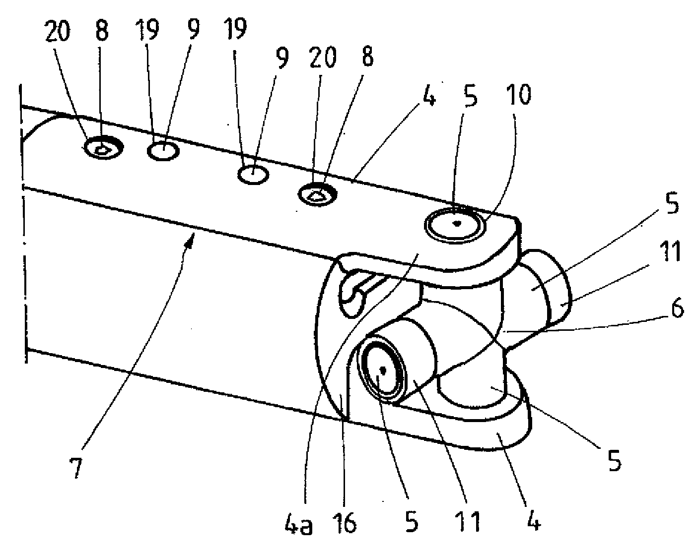
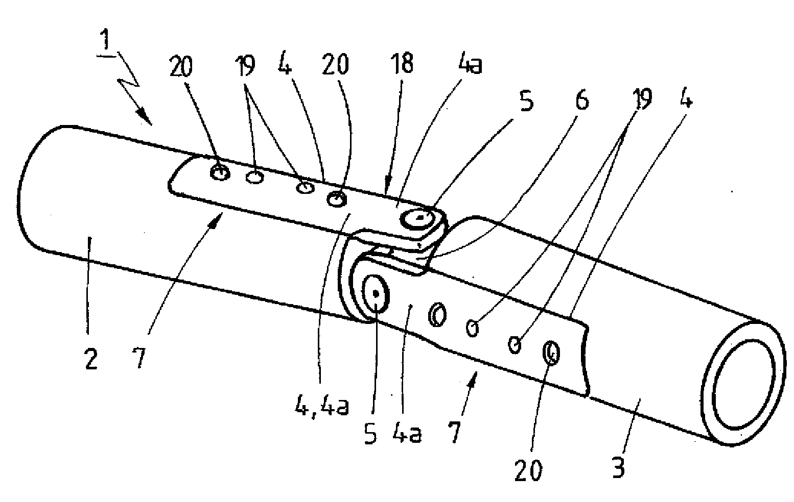
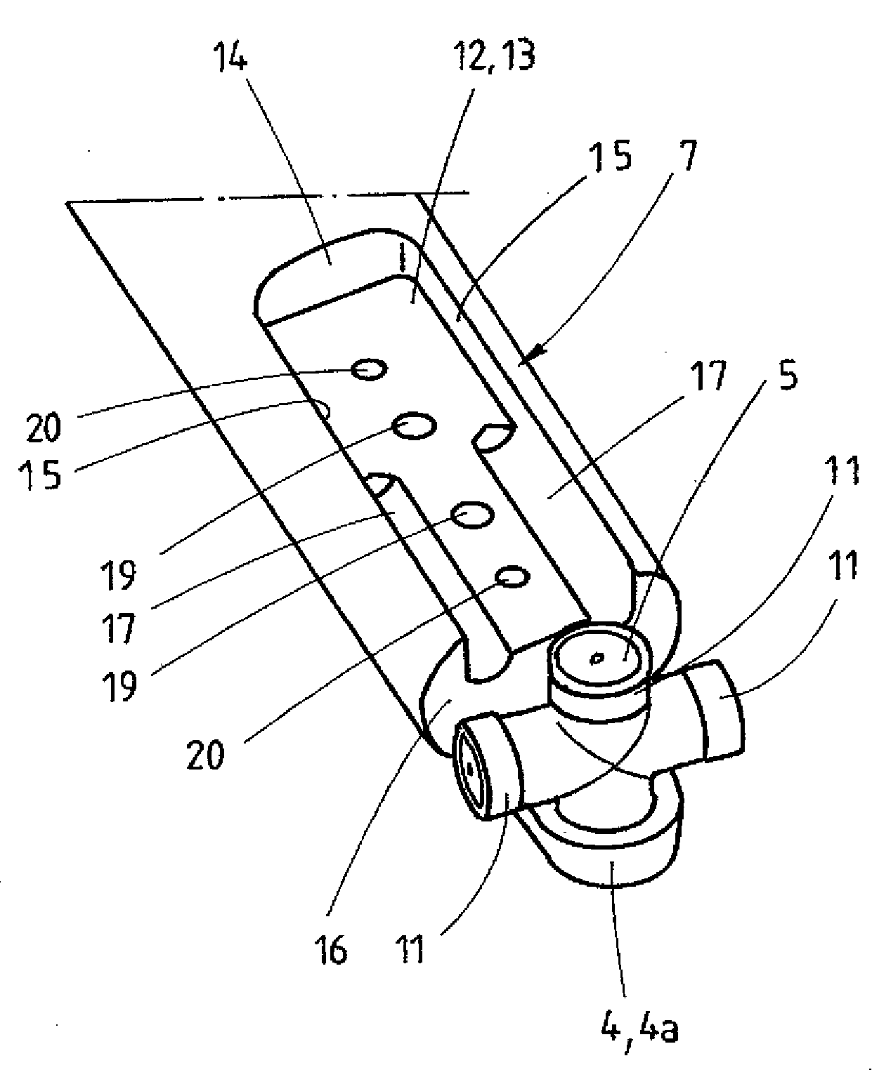
[0025] figure 1 Shows the joint area of ​​the joint 18 with the cross joint shaft designated overall at 1 with the first joint shaft section 2 and the second joint shaft section 3. Two bearing plates 4 diametrically opposite each other are arranged thereon. The bearing plates 4 protrude beyond the respectively associated first or second cardan shaft section 2 , 3 with a protruding region 4 a at one end. The projecting regions 4 a facing each other at the first or second cardan shaft section 2 , 3 respectively jointly form a fork, between which two parts of the cardan crosshead 6 constructed in one piece are held. A shaft head 5 opposite to each other. At the respective fastening regions 7 of the joint shaft sections 2 , 3 , the bearing plates 4 are each fastened by means of cylinder-head screws 8 and fastened by means of cylindrical pins 9 . The shaft studs 5 are each held in an opening 10 , a bearing bore, which is formed in the projecting region 4 a of the bearing plate 4...


PUM


Abstract

In the case of a cardan-joint shaft (1) comprising a first and a second jointed shaft portion (2, 3) and comprising bearing lugs (4) fastened in each case to a fastening region (7) of the first and second jointed shaft portions (2, 3) in particular by means of screw connections (8), which bearing lugs project in each case at one end beyond the respectively associated first or second jointed shaft portion (2, 3) and, in the projecting region (4a), hold between them a single-piece journal cross (6) which is mounted with in each case one journal (5) in an opening (10) of in each case one bearing lug (4), it is sought to provide a solution which permits the realisation of a cardan joint which is of compact construction and nevertheless permits the transmission of high torques. This is achieved in that each bearing lug (4), at least in regions, engages in a positively locking and force-transmitting manner into in each case one of two recesses (12) formed diametrically oppositely in the fastening region (7) in the outer surface, in particular circumferential surface, of the first and of the second jointed shaft portion (2, 3).

Description

technical field [0001] The invention relates to a cross cardan shaft (Kreuzgelenkwelle), which comprises a first and a second cardan shaft section (Gelenkwellenabschnitt) and a fastening area of ​​the first and second cardan shaft section, in particular by means of Bearing plate (Lagerlasche) fastened by screw connection, each end of which protrudes beyond the respectively associated first or second universal joint shaft section and in the region of this protruding holds a one-piece construction between them Universal joint crossheads, which are each mounted with shaft heads in openings in the respective bearing plate. [0002] Furthermore, the invention relates to a straightening machine with a number of straightening rollers and a drive for the straightening rollers, wherein the straightening rollers are arranged in an exchange box (Wechselkassette) and Can be connected to the main drive. Background technique [0003] The metal strip is straightened in a straightening ma...

Claims


Application Information

Patent Timeline
IPC IPC(8): F16D3/38B21B35/14
CPCB21D3/02F16D3/387B21D1/02
Inventor M.芬克R.魏斯布罗特E.穆斯塔菲
Owner SMS GRP GMBH
Why Eureka
Try Eureka