
Numerically-controlled machine tool with fixed facing head and control method thereof

A technology of CNC machine tools and flat turntables, used in automatic control devices, manufacturing tools, metal processing machinery parts, etc., can solve problems such as difficulty, low work efficiency, and inability to directly use speed shifting.

Active Publication Date: 2014-08-20
TDG MACHINERY TECH
View PDF4 Cites 1 Cited by
  • Summary
  • Abstract
  • Description
  • Claims
  • Application Information

AI Technical Summary

Problems solved by technology

[0005] The technical problem solved by the present invention is that, in the prior art, the spindle gears of the CNC machine tool with fixed flat-rotating discs include low gear, high-grade and flat-rotating disc gears. It is within the speed range of the low gear, so it is not possible to directly use the speed to shift gears, but to execute the M code to switch the mechanical transmission by controlling the gear shift solenoid valve, which leads to the operator being required to clearly Know the switching speed of high and low gears, but in fact, it is difficult for operators who generally only know the speed required for cutting, and even need to consult the manual when switching. Once the memory is wrong, it will affect the actual work, and the work efficiency is relatively low. low, thus providing an optimized CNC machine tool with a fixed flat disk and its control method

Method used


Image

  • Numerically-controlled machine tool with fixed facing head and control method thereof
  • Numerically-controlled machine tool with fixed facing head and control method thereof
  • Numerically-controlled machine tool with fixed facing head and control method thereof

Examples


Embodiment Construction

[0022] The present invention will be described in further detail below in conjunction with the examples, but the protection scope of the present invention is not limited thereto.

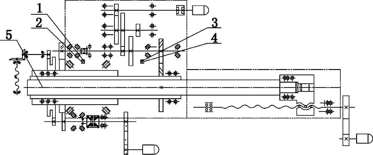
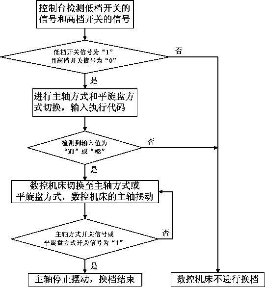
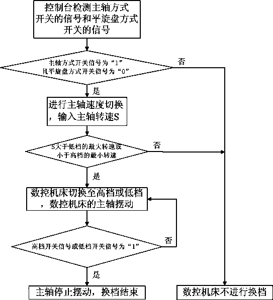
[0023] As shown in the figure, the present invention relates to a control method of a CNC machine tool with a fixed flat-rotating disk, the control method includes a spindle mode and a flat-rotating disk mode switching method and a spindle speed switching method; the console of the CNC machine tool is connected with Spindle mode switch 1, level rotary disc mode switch 2, spindle low gear switch 3 and spindle high gear switch 4;

[0024] Set "M1" on the console as the execution code for shifting gears to the spindle mode, and set "M2" as the execution code for shifting gears to the flat rotary disc mode; The rotating speed is lower than the maximum rotating speed of the high gear, the minimum rotating speed of the horizontal rotating gear is smaller than the maximum rotating speed of the horizontal r...


PUM


Abstract

The invention relates to a numerically-controlled machine tool with a fixed facing head and a control method thereof. The control method comprises a main shaft mode and facing head mode switching method and a main shaft speed switching method. A control table of the numerically-controlled machine tool is connected with a main shaft mode switch, a facing head mode switch, a main shaft low-gear switch and a main shaft high-gear switch. Signal changes of the main shaft mode switch, the facing head mode switch, the main shaft low-gear switch and the main shaft high-gear switch are utilized for switching working modes adopted by the numerically-controlled machine tool, a code M1 and a code M2 are used for switching the main shaft mode and the facing head mode, a comparison value of the rotating speed is adopted for switching the speed of a main shaft so that shifting of high and low gears can be achieved, gear shifting is controlled and finished through matching of a corresponding electromagnetic valve, and operation is safe and reliable to carry out; according to the method, operators do not need to clearly know the shifting speed of each gear and only need to know the rotating speed needed by cutting, working burdens of the operators are reduced greatly, control is easy and convenient to carry out, the work efficiency is high, the problems can be checked out easily, and excellent performance of the machine tool is ensured.

Description

technical field [0001] The invention belongs to machine tools; the technical field of metal processing and corresponding methods not included in other categories, and particularly relates to a method that satisfies the requirement that the operator only needs to know the speed required by the machine tool during cutting operations, and then can simply control the CNC machine tool to complete the compounding process. A numerically controlled machine tool with a fixed flat rotating disk and a control method thereof are processed. Background technique [0002] CNC machine tool is the abbreviation of Computer numerical control machine tools. It is an automatic machine tool equipped with a program control console. shape and size, the parts are automatically machined out. CNC machine tools solve complex, precise, small-batch, and multi-variety parts processing problems. It is a flexible, high-efficiency automatic machine tool that represents the development direction of modern ma...

Claims


Application Information

Patent Timeline
IPC IPC(8): B23Q15/007B23Q15/08
CPCB23Q15/007B23Q15/08
Inventor 杨晓红高泽辉苏静洪平志韩
Owner TDG MACHINERY TECH
Features
  • Generate Ideas
  • Intellectual Property
  • Life Sciences
  • Materials
  • Tech Scout
  • Unparalleled Data Quality
  • Higher Quality Content
  • 60% Fewer Hallucinations
Learn More