Feed lifting device of roll-dividing machine

A technology of separating and feeding materials, which is applied in the direction of coiling strips, thin material handling, transportation and packaging, etc., can solve the problems of labor-intensive, vulnerable and large rolls, and safety of workers, so as to avoid interference effects, The effect of reducing work intensity and quality assurance

Active Publication Date: 2014-08-20
SUZHOU BAIQI ELECTRONICS MATERIAL
View PDF17 Cites 8 Cited by
  • Summary
  • Abstract
  • Description
  • Claims
  • Application Information

AI Technical Summary

Problems solved by technology

Although these two methods of operation can meet the technical requirements, as far as the former is concerned, because the large roll is very heavy, the labor intensity of the workers is high, and it is accompanied by danger. As far as the latter is concerned, when the space of the production site is limited , it is difficult to equip a mechanical lifting device, especially if the operation is not careful, it is easy to damage and large rolls, and there are also safety concerns

Method used


Image

  • Feed lifting device of roll-dividing machine
  • Feed lifting device of roll-dividing machine

Examples


Embodiment

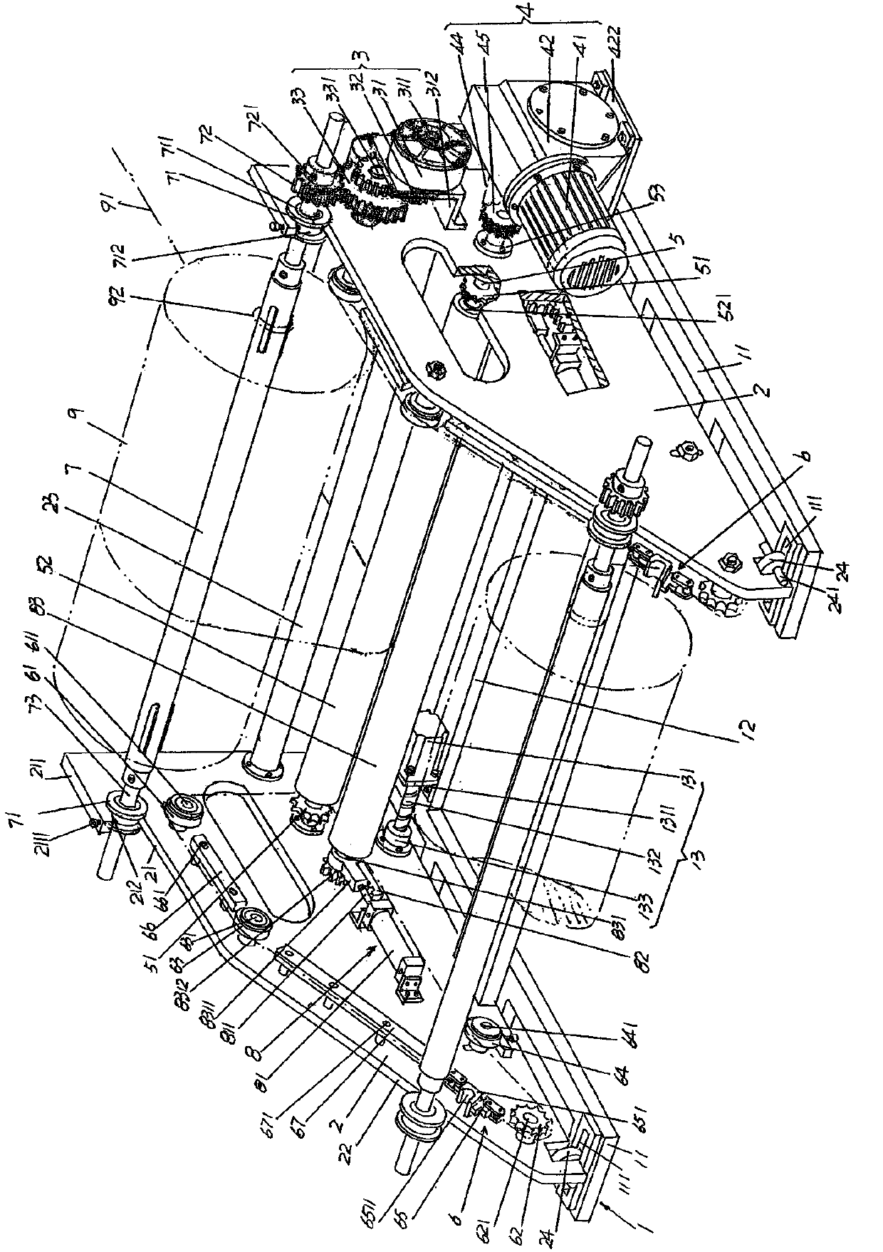
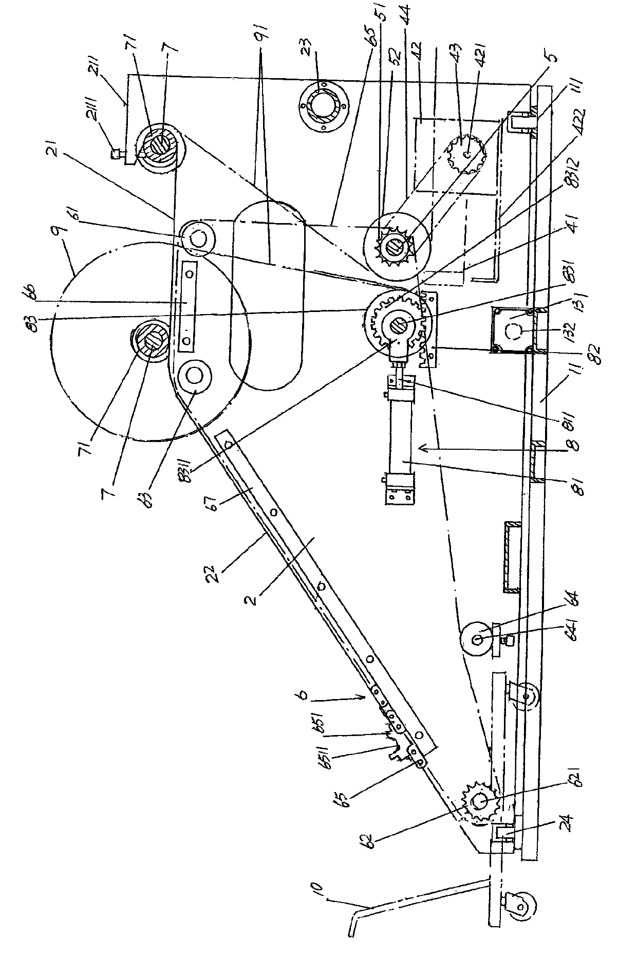
[0023] See figure 1 , A frame 1 belonging to the structural system of the sub-winding machine is given, and the frame 1 can also be called a base or a chassis. by figure 1 It can be seen that the base 1 is composed of a pair of base arms 11 parallel to each other and a base arm connecting beam 12 for connecting the pair of base arms 11 into a solid overall structure. As a preferred solution, a pair of base arms 11 The front and rear ends of the arm 11 ( figure 1 (Shown in the position state) each of the components is to provide a wallboard roller groove 111, and the function of the wallboard roller groove 111 will be described below.

[0024] A pair of wall panels 2 that also belong to the structural system of the sub-winding machine is given. The pair of wall panels 2 are set on the machine base 1 in a state of facing each other and are fixedly connected to each other, specifically: a pair of wall panels One of the wall panels in 2, that is, the wall panel on the left is set on ...


PUM


Abstract

The invention discloses a feed lifting device of a roll-dividing machine, and belongs to the field of devices special for thin film adhesive tape production. The roll-dividing machine comprises a machine base, a pair of wall plates and a carrier roller driving mechanism, wherein the wall plates form a carrier roller horizontal roller path and a carrier roller crawling roller path respectively, the end, away from the carrier roller crawling roller path, of the carrier roller horizontal roller path forms a wall plate blocking shoulder, the space between the wall plate blocking shoulder and the carrier roller horizontal roller path forms a carrier roller unrolling cavity, and the carrier roller driving mechanism is arranged on the side, facing outwards, of one wall plate. The feed lifting device comprises a carrier roller lifting power mechanism, a traction transmission shaft, a carrier roller traction mechanism and a carrier roller, wherein the traction transmission shaft is supported between the pair of wall plates, the carrier roller traction mechanism is connected with the traction transmission shaft, and the carrier roller is firstly matched with the carrier roller traction mechanism in the use state and dragged from the carrier roller crawling roller path to the carrier roller horizontal roller path through the carrier roller traction mechanism and is then matched with the carrier roller driving mechanism after entering the carrier roller unrolling cavity from the carrier roller horizontal roller path. Work intensity is lowered, the overall structure is simple, production space is saved, quality of thin film adhesive tape is ensured, and safety of online workers is protected.

Description

Technical field [0001] The invention belongs to the technical field of special equipment in the production of film adhesive tapes, and specifically relates to a feeding and lifting device of a sub-winding machine. Background technique [0002] The above-mentioned film adhesive tapes, such as various types of masking tapes including shading tapes, can be found in CN101245226A (a new type of shading tape), CN202626083U (translucent tape), CN202808680U (used for LCD module tape), CN202808683U (light-shielding reflective tape for electronic products), CN202808684U (light-shielding double-sided tape for electronic products), CN102149780A (covering strip of PVC film), etc. [0003] Take the technical content disclosed in the "PCB board light-shielding tape and its preparation method" recommended by the invention patent application publication number CN103342969A as an example. The steps include: selecting the substrate and pretreating the substrate, that is, electrically conducting both...

Claims


Application Information

Patent Timeline
Patent Type & Authority Applications(China)
IPC IPC(8): B65H19/30
Inventor 朱海云朱泽燕
Owner SUZHOU BAIQI ELECTRONICS MATERIAL
Why Eureka
Try Eureka