A liquid crystal display and its driving method

A technology of liquid crystal display and driving mode, applied in static indicators, instruments, etc., can solve the problem of sub-pixel units not being able to be charged, and achieve the effect of improving quality

Active Publication Date: 2017-01-18
XIAMEN TIANMA MICRO ELECTRONICS +1
View PDF5 Cites 0 Cited by
  • Summary
  • Abstract
  • Description
  • Claims
  • Application Information

AI Technical Summary

Problems solved by technology

[0007] The purpose of the present invention is to provide a liquid crystal display and its driving method, which is used to solve the problem in the prior art that the sub-pixel units cannot be charged to the required voltage as the resolution increases

Method used


Image

  • A liquid crystal display and its driving method
  • A liquid crystal display and its driving method
  • A liquid crystal display and its driving method

Examples


Embodiment 1

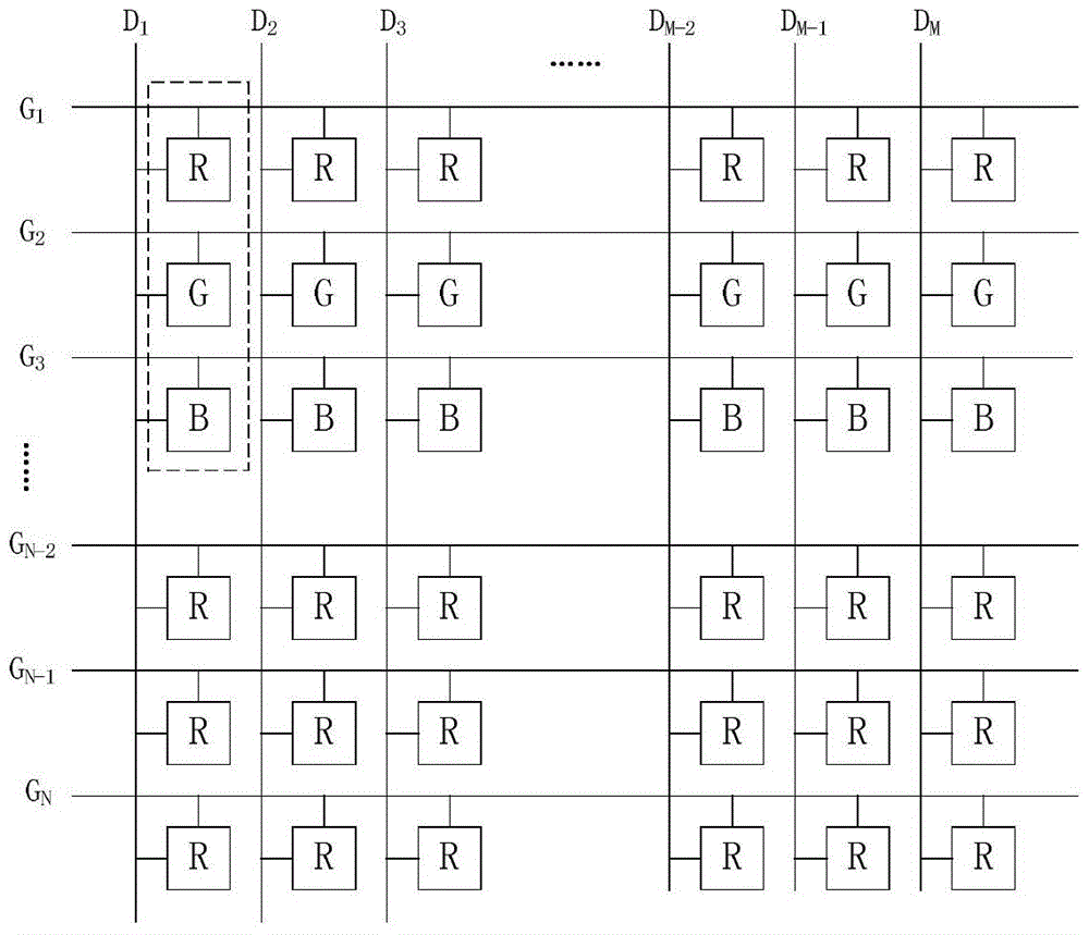
[0022] figure 1 It is a schematic diagram of the pixel unit array structure of the liquid crystal display in Embodiment 1 of the present invention, as figure 1 As shown, the pixel unit array of the liquid crystal display includes a plurality of data lines and a plurality of scan lines, wherein the data lines are arranged along the vertical direction and parallel to each other, as shown in FIG. figure 1 shown on the data line D 1 , data line D 2 , data line D 3 , ... data line D M-2 , data line D M-1 , data line D M , where M is a positive integer, and the scan lines are arranged along the transverse direction and parallel to each other, such as figure 1 The scan line G shown 1 , scan line G 2 , scan line G 3 , ... scan line G N-2 , scan line G N-1 , scan line G N , where N is a positive integer. The plurality of data lines and the plurality of scan lines intersect to define a plurality of sub-pixels, and the plurality of sub-pixels are arranged in an array. Where...

Embodiment 2

[0038] Figure 4 It is a schematic diagram of the pixel unit array structure of the liquid crystal display in Embodiment 2 of the present invention, as Figure 4 As shown, the pixel unit array structure of the liquid crystal display includes a plurality of data lines and a plurality of scan lines, wherein the data lines are arranged in the vertical direction and parallel to each other, as shown in Figure 4 shown on the data line D 1 , data line D 2 , data line D 3 , data line D 4 , data line D 5 and data line D 6 . The scan lines are aligned in the lateral direction and parallel to each other, as figure 1 The scan line G shown 1 and scanline G 2 . In addition, the plurality of data lines and the plurality of scanning lines intersect a plurality of sub-pixels, wherein the plurality of sub-pixels may be three sub-pixels of red (abbreviated as R), green (abbreviated as G), and blue (abbreviated as B). One of.

[0039] exist Figure 4 In the pixel unit array structur...


PUM


Abstract

The invention provides a liquid crystal display (LCD) driving mode. The LCD comprises a plurality of pixel units, each pixel unit comprises three sub-pixels, and is characterized in that in one charging process, any two sub-pixels are charged at first, then the third sub-pixel is charged; in the next charging process, the third sub-pixel is charged at first; in the one charging process, the charging times of the two sub-pixels that are charged at first are equal and longer than that of the third sub-pixel, and one complete charging process means that all three sub-pixels are all charged. On the basis that the resolution is increased and the refresh rate is not changed, the LCD can guarantee the sufficient charging of sub-pixels, thus avoids the color difference, and improves the quality of display frame.

Description

technical field [0001] The invention relates to the field of liquid crystal displays, in particular to a liquid crystal display and its driving method. Background technique [0002] With the continuous development of liquid crystal display technology, liquid crystal display (Liquid Crystal Display, LCD), which has the advantages of small size, low power consumption, and no radiation, has gradually replaced cathode ray tube (Cathode Ray Tube, CRT) display as the display device. Mainstream products are gradually and widely used in various electronic products. [0003] In the prior art, the pixel driving structure of traditional TFT (Thin Film Transistor, Thin Film Field Effect Transistor) LCD generally includes data line (Data Line, also called Source Line), scan line (Gate Line, also called gate line) , wherein the data lines are vertically arranged in columns and parallel to each other, the scanning lines are horizontally arranged in rows and parallel to each other, and the...

Claims


Application Information

Patent Timeline
Patent Type & Authority Patents(China)
IPC IPC(8): G09G3/36
Inventor 李元杨贤艳
Owner XIAMEN TIANMA MICRO ELECTRONICS
Why Eureka
Try Eureka