
LED illumination control circuit for silicon controlled light modulator to achieve light and color synchronous adjustment and method thereof

A technology for LED lighting and control circuits, applied in lighting devices, lamp circuit layout, light sources, etc., can solve the problems of incompatibility with thyristor dimming, complex control circuits, and high cost, and achieve compact and flexible control circuits and simple overall design. , the effect of strong transplantation

Active Publication Date: 2014-08-20
HENGDIAN GRP TOSPO LIGHTING
View PDF6 Cites 14 Cited by
  • Summary
  • Abstract
  • Description
  • Claims
  • Application Information

AI Technical Summary

Problems solved by technology

[0006] 1. Synchronous color temperature cannot be achieved while dimming
[0007] 2. There must be more than two LED loads, which is not conducive to cost control
[0008] 3. The use of PWM signal control is not conducive to the miniaturization design of the LED integrated light source
[0009] 4. MCU is used to programmably control each output circuit, the control circuit is complicated and the cost is high
[0010] 5. Not compatible with thyristor dimming

Method used


Image

  • LED illumination control circuit for silicon controlled light modulator to achieve light and color synchronous adjustment and method thereof
  • LED illumination control circuit for silicon controlled light modulator to achieve light and color synchronous adjustment and method thereof
  • LED illumination control circuit for silicon controlled light modulator to achieve light and color synchronous adjustment and method thereof

Examples


Embodiment Construction

[0044] The present invention will be further described in detail below in conjunction with the embodiments and the accompanying drawings, but the embodiments of the present invention are not limited thereto.

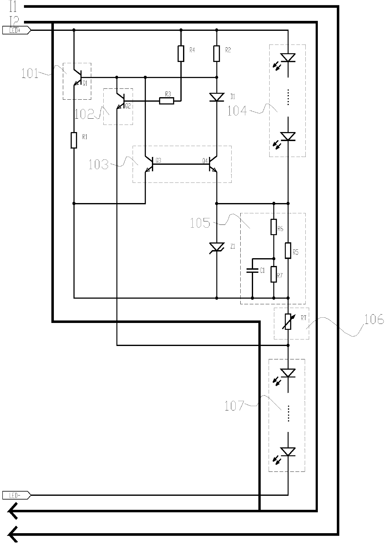
[0045] refer to figure 2 and image 3 , figure 2 It is a functional block diagram of the existing SCR dimmer to realize dimming. The conventional SCR dimming circuit connects the SCR dimmer 201 in series at the input end of the AC power supply, passes through the EMI filter network 202, and then rectifies and filters The circuit 203 rectifies the alternating current into direct current, and then outputs and lights up the LED load 205 through the driving and dimming control circuit 204, and at the same time realizes the dimming function, image 3 According to the LED lighting control circuit diagram applicable to the thyristor dimmer to realize synchronous dimming and color adjustment according to the present invention, in the implementation process, when the thyristo...


PUM


Abstract

The invention discloses an LED illumination control circuit for a silicon controlled light modulator to achieve light and color synchronous adjustment and a method thereof. The control circuit comprises a bypass amplifying circuit, a bypass switching circuit, a self-adaptive detection circuit, LED modules, a color temperature adjusting depth control point circuit and a color temperature adjusting start point control circuit. The bypass amplifying circuit, the bypass switching circuit, the self-adaptive detection circuit, the color temperature adjusting depth control point circuit and the color temperature adjusting start point control circuit are connected in sequence. The LED modules are respectively connected with the bypass amplifying circuit, the bypass switching circuit, the self-adaptive detection circuit and the color temperature adjusting depth control point circuit. According to the method, the different current magnitudes of the first LED module and the second LED module are synchronously controlled, color mixture happens to the LED modules with different color temperatures, and the luminance rate is changed. Light and color modulation detection and control circuits are additionally arranged at the two ends of an LED load, the color temperature can be changed synchronously while light modulation is conducted on the silicon controlled light modulator, and therefore the synchronous light and color adjusting function can be achieved.

Description

technical field [0001] The invention relates to an LED control circuit technology, in particular to an LED lighting control circuit and method for a thyristor dimmer to realize light color coherence. Background technique [0002] Nowadays, energy-saving and environment-friendly light sources using LED are more and more widely used. With the development of LED technology, people's requirements for light quality are also getting higher and higher. Adjusting the brightness and adjusting the color temperature can meet the needs of many customers for light changes, and the change of LED luminous ability is gradually changing people's lives. [0003] At present, the way to realize adjustable light and adjustable color is mainly realized by RGB mixed light and color. The LED load adopts three basic color temperatures of red, green and blue. By controlling the working current of the three color temperature LEDs, the various color temperature LEDs The brightness is controlled to ach...

Claims


Application Information

Patent Timeline
Patent Type & Authority Applications(China)
IPC IPC(8): H05B37/02
Inventor 陈亮
Owner HENGDIAN GRP TOSPO LIGHTING
Learn More