Transfer assembly

A technology of transmission components and components, applied in the direction of electrical components, parts of protection switches, protection switch operation/release mechanisms, etc.

Active Publication Date: 2014-08-20
SIEMENS AG
View PDF6 Cites 4 Cited by
  • Summary
  • Abstract
  • Description
  • Claims
  • Application Information

AI Technical Summary

Problems solved by technology

Such a delay time is realized in transmissions known from the prior art by a mass arranged on the shaft, which delays the rotational movement of the shaft and thus transmits the switching process of the safety tripping device to the switching device with a delay. on the drive

Method used


Image

  • Transfer assembly
  • Transfer assembly

Examples


Embodiment Construction

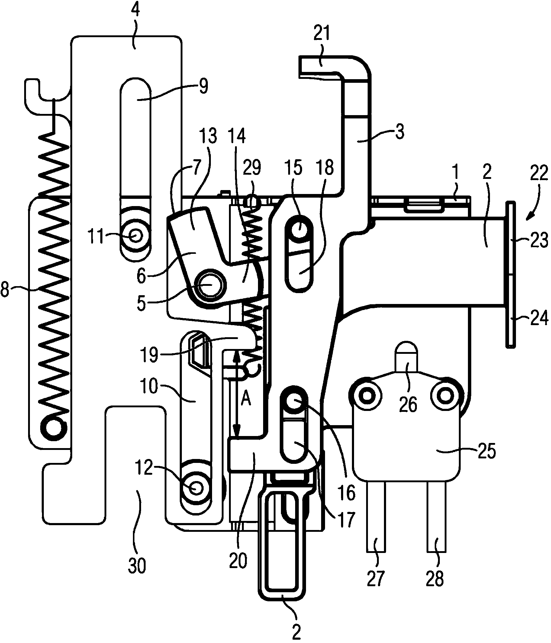
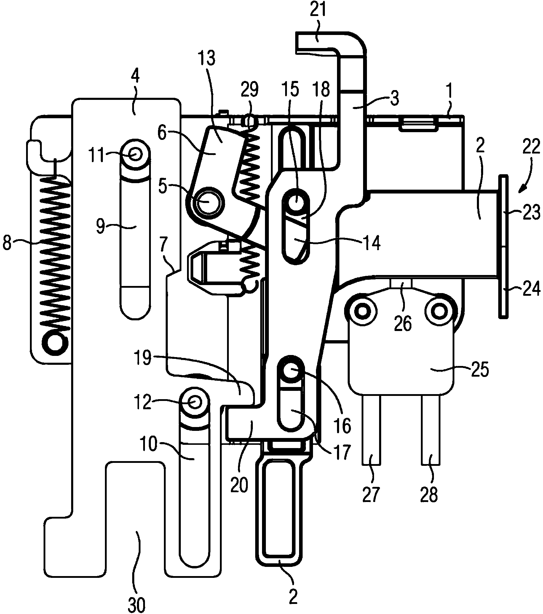
[0014] figure 1 It shows a transmission assembly, which is used to transmit the triggering of the safety device of the HH safety device not shown in the figure, such as the triggering of the safety device of the medium voltage switchgear, and the safety device triggering tappet and the movable support are not shown in the figure The first lever 2 on the support element 1 is mechanically coupled to the drive of the switching device of the medium-voltage switchgear, also not shown in the figure, which is actuated by the second lever 3, which is also movably supported on the support element 1 , wherein the transmission assembly is designed to delay triggering the switching process of the switching device not shown in the figure when the safety device has been triggered, in such a way that the safety device trigger mechanism is transmitted to the second lever 3 with delay through the first lever 2 and the transmission assembly superior. The weight element 4 of the transmission as...


PUM


Abstract

In order to form a transfer assembly with a simple and cost-effective structure for coupling a protection device triggering mechanism to a drive of a switching device with delaying means for delayed triggering of the switching process for the switching device when the protection device has triggered, it is proposed that the delaying means has a first lever (2), which is coupled to the protection device triggering mechanism and locks a weight element (4), which can be moved vertically between a first and a second position, in the first position via a latch arrangement (5, 6) and releases it when the protection device triggers, and a second lever (3), which is provided in order to actuate the drive and which can be actuated by the weight element (4); the weight element (4) can be transferred into its second position by means of the weight force thereof and a force exerted onto the weight element (4) by a first spring (8).

Description

technical field [0001] The invention relates to a gear unit for coupling a safety device tripping mechanism with a drive of a switching device, which has delay means for delaying the switching process of the tripping switching device when the safety device has tripped. Background technique [0002] Such a transmission assembly is known from WO 03 / 069647 A1 and comprises a transmission for coupling the tripping mechanism of the safety device with the driver of the switching device. The transmission mechanism includes delay means for triggering the switching process of the switching device with a delay when the safety device has been tripped, the delay means being designed in the form of a momentum wheel arranged on the shaft, the mass of which delays the rotational movement of the shaft and leads to contact with the transmission Delayed switching process of mechanically coupled switching devices. Such transmissions are provided, for example, in medium-voltage switchgears whi...

Claims


Application Information

Patent Timeline
Patent Type & Authority Applications(China)
IPC IPC(8): H01H71/12H01H71/44H01H85/30
CPCH01H85/306H01H71/122H01H71/446
Inventor R.兹利德尼克
Owner SIEMENS AG
Why Eureka
Try Eureka