Pipettor

A pipette and liquid circuit technology, applied in the field of laboratory equipment, can solve the problem of inability to set a liquid level detection device, etc., and achieve the effects of compact and reasonable structure design, stable movement process and small size

Active Publication Date: 2014-08-27
SHANGHAI UNITED INTELLIGENCE ROBOTICS INC
View PDF5 Cites 10 Cited by
  • Summary
  • Abstract
  • Description
  • Claims
  • Application Information

AI Technical Summary

Problems solved by technology

The liquid level detection device

Method used


Image

  • Pipettor
  • Pipettor
  • Pipettor

Examples


Embodiment 1

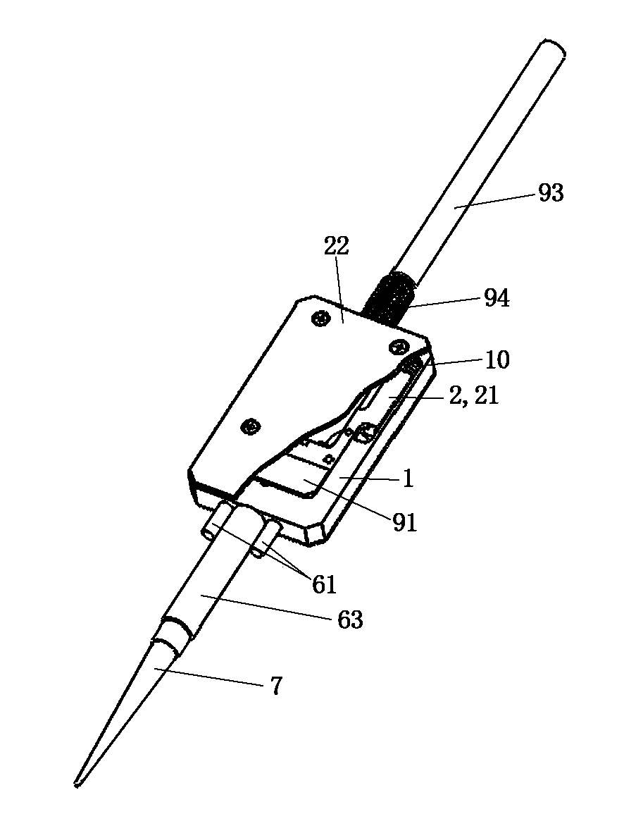
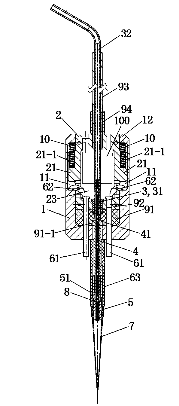
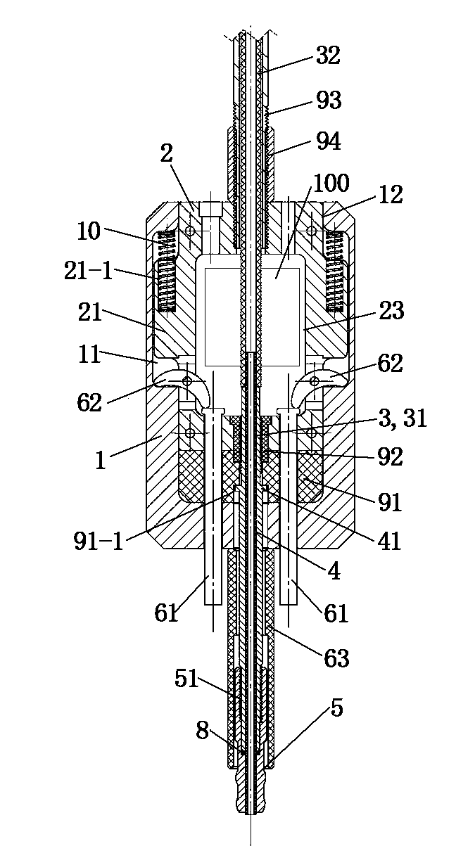
[0038] See Figure 1 to Figure 3, the pipette of this embodiment includes an outer frame 1, an inner frame 2, a liquid pipe 3, a ball head connecting rod 4, a ball head 5, a suction tip withdrawal mechanism 6, a suction head 7, a power rod 93 and a power rod nut 94 . The top of the outer frame 1 is provided with an opening 12 , and the top of the inner frame 2 is located in the opening 12 . The power rod 93 passes through the top of the inner frame 2 and is screwed with the inner frame 2 . The power rod nut 94 is screwed on the power rod 93 , and the power rod nut 94 abuts against the top of the inner frame 2 from above. The inner frame 2 is provided with a cavity 23 . The top of the inner frame 2 is provided with a groove communicating with the cavity 23 of the inner frame 2 for wiring.

[0039] Both sides of the inner wall of the outer frame 1 are respectively provided with grooves 11 . Both sides of the inner frame 2 are respectively provided with protrusions 21 locate...


PUM


Abstract

The invention relates to a pipettor which comprises an outer frame, an inner frame, a liquid path pipe, a ball head connecting rod, a ball head and a de-sucking head mechanism, wherein the inner frame is fixedly connected with a power rod and is driven to move by the power rod; the outer frame is suitable for sliding up and down along the inner frame; the ball head connecting rod penetrates through the inner and outer frames; the top end of the ball head connecting rod is fixedly connected with the inner frame and is electrically insulated with the inner frame; the ball head is fixed at the bottom end of the ball head connecting rod and is used for clamping a suction head; the liquid path pipe vertically penetrates through the inner and outer frames, and passes through the ball head connecting rod and the ball head; the de-sucking head mechanism comprises an ejector pin, a rocker and a sleeve; the sleeve is arranged at the bottom of the outer frame, and is arranged outside the ball head connecting rod and the ball head in a sleeving manner, and is opposite to the position of the suction head; the top end of the ejector pin is limited in a hollow cavity of the inner frame; the ejector pin is suitable for sliding up and down along the inner frame; the rocker and the inner frame are hinged, one end of the rocker props against the top end of the ejector pin and the other end of the rocker props against the outer frame. The pipettor is compact in structure, is used for automatically extracting the suction head and the de-sucking head when medical/chemical and various measuring devices transfer liquid and is capable of detecting whether the suction head is in contact with the liquid surface.

Description

technical field [0001] The invention relates to a pipetting device, which belongs to the technical field of laboratory equipment. Background technique [0002] The pipette is a small-capacity pipetting device commonly used in laboratories, and is widely used in clinical diagnostic laboratories, biotechnology laboratories, pharmaceutical and chemical laboratories, environmental laboratories, food laboratories, etc. With the continuous improvement of the automation of various laboratory machinery, automated assembly line workstations are gradually becoming the protagonists in the laboratory. In order to absorb, move, and load trace amounts of liquid more accurately, the design requirements for pipettes are also increasing. [0003] Chinese patent document CN103691498 (application number: 201410004737.0) discloses a pipette and a method for pipetting liquid using it. The pipette includes a base, a column on one side of the base, a Z-axis motor on the column, The first screw ro...

Claims


Application Information

Patent Timeline
IPC IPC(8): B01L3/02
Inventor 朱海鸿
Owner SHANGHAI UNITED INTELLIGENCE ROBOTICS INC
Why Eureka
Try Eureka