
Multi-station rotary support special for rotary washing device

A multi-station and equipment technology, applied in cleaning methods and tools, cleaning methods using liquids, chemical instruments and methods, etc., can solve problems affecting wafer cleaning effects, high dynamic balance value, and decreased wafer cleanliness

Active Publication Date: 2014-08-27
THE 45TH RES INST OF CETC
View PDF5 Cites 19 Cited by
  • Summary
  • Abstract
  • Description
  • Claims
  • Application Information

AI Technical Summary

Problems solved by technology

The traditional turntable with only one wafer box placement body has the following defects: 1. The wafer cleaning efficiency is low due to the small number of wafers placed on the turntable; Rotation center and drying effect are poor; 3, the wafer box takes the turntable rotation center as the rotation center, and its transverse section of the wafer box and the placement body for placing the wafer box is an irregular surface, and some structural points are close to the center of rotation, and there are The structure point is far away from the rotation center point, and the dynamic balance value is high during the rotation of the turret
Microparticles produced under dynamic balance vibration will affect the cleaning effect of the wafer, resulting in a decrease in the cleanliness of the wafer and a decrease in the qualified rate of finished products

Method used


Image

  • Multi-station rotary support special for rotary washing device
  • Multi-station rotary support special for rotary washing device
  • Multi-station rotary support special for rotary washing device

Examples


Embodiment Construction

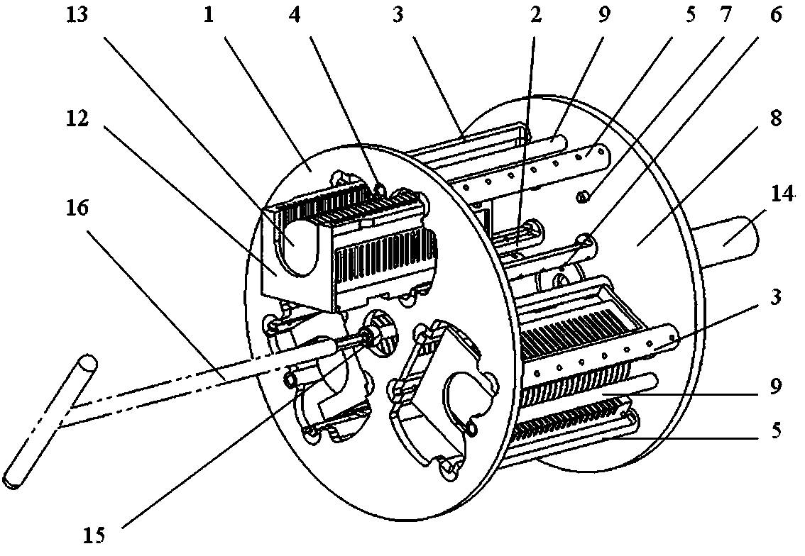
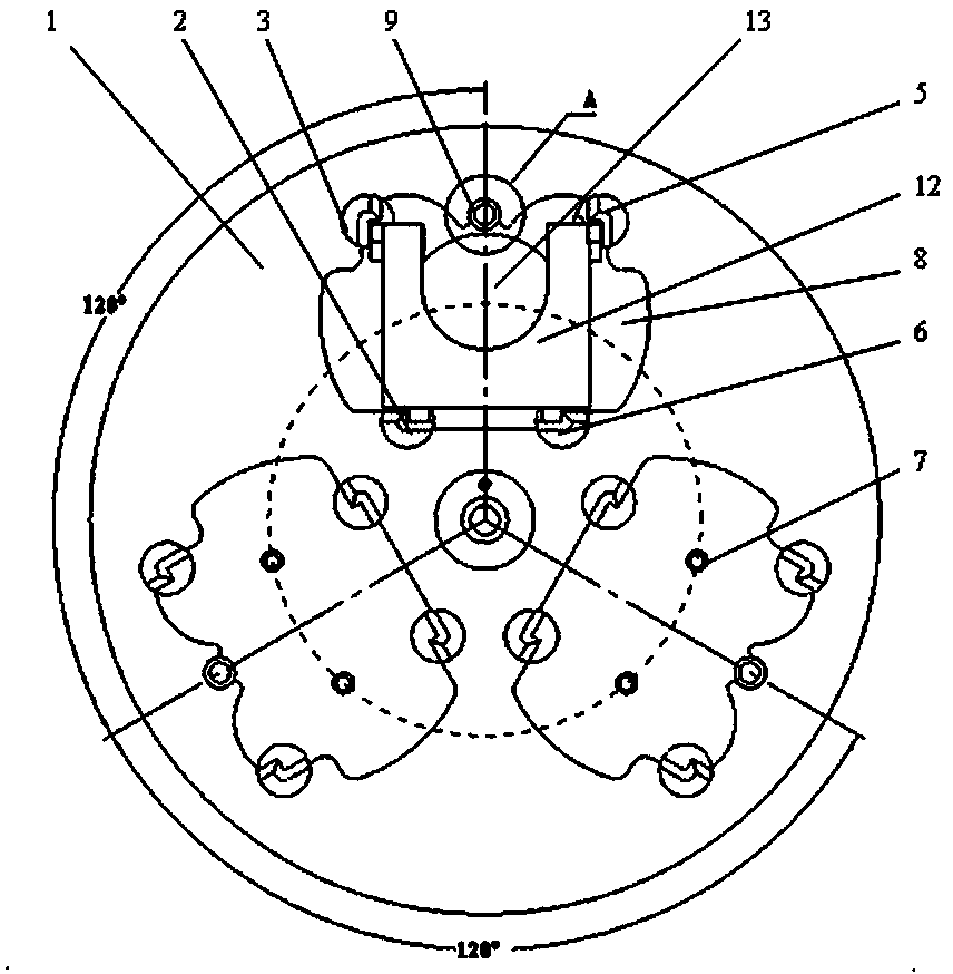
[0020] like figure 1 , figure 2 As shown, the multi-station turntable dedicated to the rotary washing equipment of the present invention includes a front tray 1 and a rear tray 8, and three stations for placing wafer cassettes 12 are arranged between the front tray 1 and the rear tray 8. The outer surface of the front plate 1 is provided with three wafer box inlets and outlets. A wafer box inlet and outlet and a station form a group of station structures. The axis lines of the three groups of station structures are all parallel to and at equal distances from the rotation axis lines of the special multi-station turntable for rotary washing equipment. The three sets of station structures are evenly distributed at 120° in the special multi-station turntable for rotary washing equipment.

[0021] like figure 1 , figure 2 , image 3 , Figure 4 , Figure 5 , Figure 7 As shown, each group of station structures includes an outer left strut 3, an outer right strut 5, an in...


PUM


Abstract

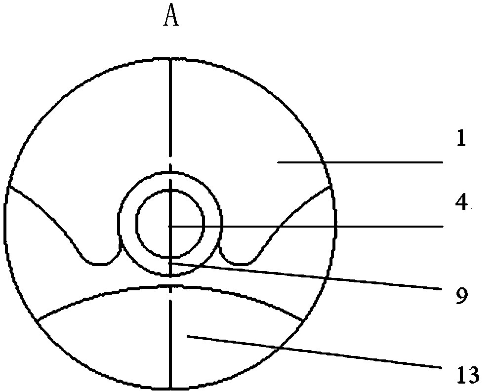
The invention relates to a multi-station rotary support special for a rotary washing device. The multi-station rotary support comprises a front disc and a back disc, three station structures for containing chip boxes are formed between the front disc and the back disc by welding three sets of inner and outer left supporting rods, inner and outer right supporting rods and pressing rods. The pressing rods are sleeved with damping sleeves in a connected mode to be used for limiting movement of chips under the centrifugal force effect. The position, below the damping sleeves, of the inner side of the back disc is provided with small cushion blocks in a welding mode for limiting the positions of the chip boxes, and the position, at the position of a center hole, of the outer side of the back disc is provided with a hollow driven shaft and a transmission key in a welded mode to be used for being connected with a motor output shaft. The station structures are circumferentially and evenly distributed around the center of the rotary support, the problem that the chip washing effect is influenced by microparticles generated when the dynamic equilibrium value is high is solved, and the chip washing quality is remarkably improved. The multi-station rotary support is driven by a motor to be capable of simultaneously carrying the chips in the three chip boxes to conduct rotary washing, the chips are far away from the rotating center of the multi-station rotary support special for the rotary washing device, spin-drying is easily carried out in one work procedure, the production efficiency is greatly improved, and the production cost is reduced.

Description

technical field [0001] The invention relates to a wafer rinsing device, in particular to a multi-station turntable dedicated to the rotary rinsing device. Background technique [0002] In IC and related industries, spin rinse equipment is an indispensable tool for wafer cleaning, and the turret of spin rinse equipment is an important device on wafer rinse tool. During production, wafers are placed in wafer cassettes, which are installed on the turntable of the rotary washing device, and the motor drives the turntable to rotate to rinse the wafers in the wafer cassette. The turntable of the traditional rotary rinsing equipment is provided with only one wafer cassette placement body, which can only carry one wafer cassette and rinse a small amount of wafers. The traditional turntable with only one wafer box placement body has the following defects: 1. The wafer cleaning efficiency is low due to the small number of wafers placed on the turntable; Rotation center and drying ef...

Claims


Application Information

Patent Timeline
IPC IPC(8): B08B13/00
CPCB08B3/022
Inventor 关宏武舒福璋姚立新段成龙冯小强
Owner THE 45TH RES INST OF CETC
Learn More