Continuous extrusion mold for C-shaped slot row

An extrusion die and C-groove technology, applied in the direction of metal extrusion dies, etc., can solve problems such as easy breakage, inability to continuously extrude, product dimensional accuracy, and surface quality cannot be effectively controlled, so as to reduce load and product The effect of stable quality

Inactive Publication Date: 2014-08-27
TAIXING SHENGDA COPPER IND CO LTD
View PDF6 Cites 5 Cited by
  • Summary
  • Abstract
  • Description
  • Claims
  • Application Information

AI Technical Summary

Problems solved by technology

The traditional C-shaped groove row extrusion method is water seal extrusion after ingot casting, and the dimensional accuracy and surface quality of the extruded products cannot be effectively controlled
However, when the general continuous extrusion core is extruding the C-shaped groove row, some parts are easy to break and cannot be continuously extruded.

Method used


Image

  • Continuous extrusion mold for C-shaped slot row
  • Continuous extrusion mold for C-shaped slot row
  • Continuous extrusion mold for C-shaped slot row

Examples


Embodiment Construction

[0016] Below in conjunction with accompanying drawing, the specific embodiment of the present invention is described in further detail:

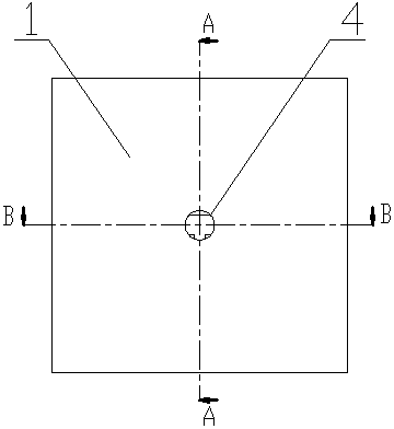
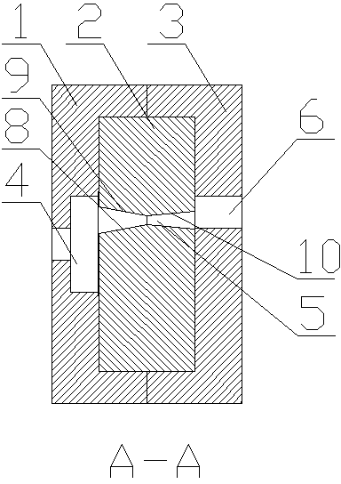
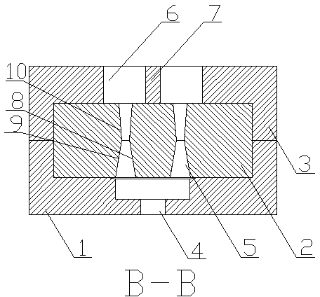
[0017] Such as figure 1 , 4 As shown, a C-shaped groove row continuous extrusion die includes a front cover 1, a mold core 2 and a rear cover 3. After the front cover 1 and the rear cover 3 are molded together, a columnar cavity is formed, and the mold core 2 is fixedly installed on the In the mold cavity, the center of the front cover 1 is provided with a circular channel 3, the center of the mold core 2 is provided with a C-shaped cavity 5, the center of the back cover 3 is provided with a rectangular channel 6, and the center line of the rectangular channel 6 is provided with a convex The platform 7, the circular channel 4, the C-shaped cavity 5, and the rectangular channel 6 are sequentially connected to form a C-shaped groove row extrusion channel.

[0018] Such as figure 2 , 3 As shown, the circular channel is...


PUM


Abstract

The invention relates to a continuous extrusion mold for a C-shaped slot row. The continuous extrusion mold for the C-shaped slot row comprises a front cover, a rear cover and a mold core, wherein the front cover and the rear cover are connected with each other in a closed manner to form a cavity; the mold core is arranged in the cavity; a circular channel is formed in the center of the front cover; a C-shaped mold cavity is formed in the center of the mold core; a rectangular channel is formed in the center of the rear cover; the circular channel, the C-shaped mold cavity and the rectangular channel are communicated with one another in sequence; taper angles are arranged at the outlets of the circular channel to increase the transverse flow of a material; an outer taper angle and an inner taper angle are arranged at the inlet and the outlet of the C-shaped mold cavity so as to effectively reduce the load of the middle part of the C-shaped slot row; a boss is additionally arranged on the rear cover of a cavity body, so that the middle part of the C-shaped slot row is effectively supported, the continuous extrusion of the C-shaped slot row is guaranteed, and the product quality is stable.

Description

technical field [0001] The invention relates to a die, in particular to a C-shaped groove row continuous extrusion die. Background technique [0002] C-shaped trough row is an essential material for power transmission in the power transmission and transformation industry. The C-shaped groove row has the characteristics of anti-deformation, energy saving, and optimization of the space of the complete set of switchgear. It is suitable for some occasions that have special cross-sectional shape requirements for conductive materials, and can meet the requirements for the replacement and upgrading of complete sets of switchgear. The traditional C-shaped groove row extrusion method is water seal extrusion after ingot casting, and the dimensional accuracy and surface quality of the extruded products cannot be effectively controlled. However, the general continuous extrusion core is prone to partial fracture when extruding the C-shaped groove row, which cannot be continuously extru...

Claims


Application Information

Patent Timeline
Patent Type & Authority Applications(China)
IPC IPC(8): B21C25/02
Inventor 赵重庆钱峰谢鑫
Owner TAIXING SHENGDA COPPER IND CO LTD
Why Eureka
Try Eureka