Cable weaving tin dipping device and method

A cable and tin dipping technology, which is applied in the field of cable processing equipment, can solve the problems of solder position drop, uneven braid tin dipping, easy solidification, etc., achieve consistent length, improve tin dipping effect, and ensure quality

Active Publication Date: 2014-08-27
KUNSHAN XUNTAO PRECISION MACHINERY
View PDF9 Cites 2 Cited by
  • Summary
  • Abstract
  • Description
  • Claims
  • Application Information

AI Technical Summary

Problems solved by technology

[0002] Cable is a commonly used signal transmission line in the electronics industry. It is usually composed of conductors, insulators, braids and jackets. The quality of the cable is directly related to whether the entire electrical equipment can work normally. During the cable processing process, it is necessary to first The outer part of the cable head is stripped, and then the braiding of the cable is tinned, which is convenient for subsequent processing. However, during the tinning process of the cable braiding in the tin furnace, after a period of time, due to the use of tin material, the tin The tin surface of the furnace will drop. If the cable is still lowered into the original height of the tin furnace, the position of the tin material will drop, resulting in inconsistent lengths of tin dipping before and after, which will affect the quality of the product. In addition, the tin material will become liquid during the dipping process. Shaped tin is easy to solidify, which will cause uneven tinning of the braid, and inconsistent tin thickness, which affects the tinning effect of the cable braid

Method used


Image

  • Cable weaving tin dipping device and method
  • Cable weaving tin dipping device and method
  • Cable weaving tin dipping device and method

Examples


Embodiment Construction

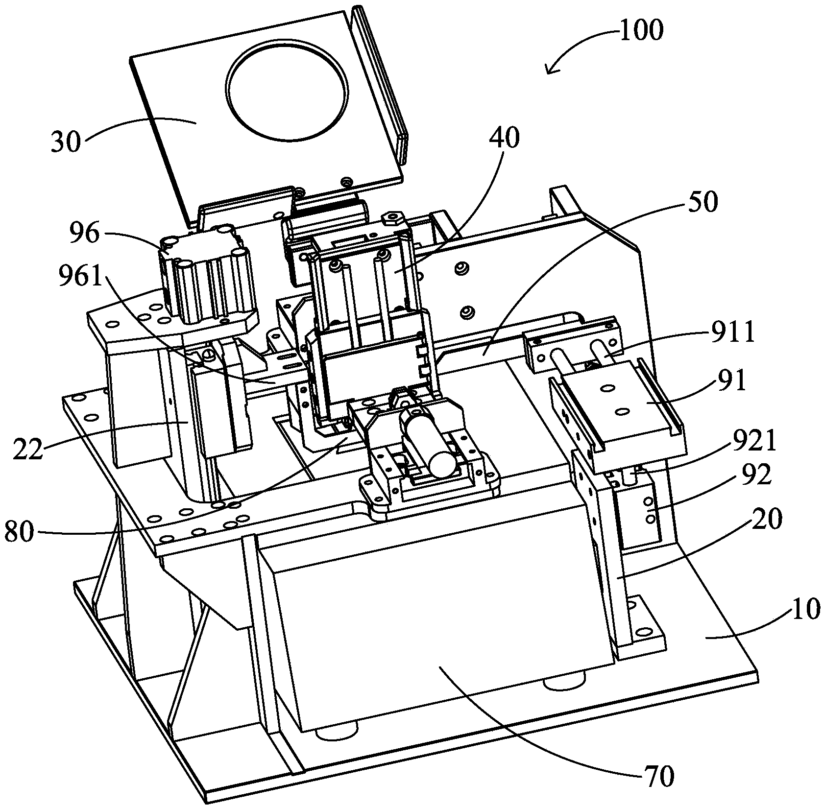
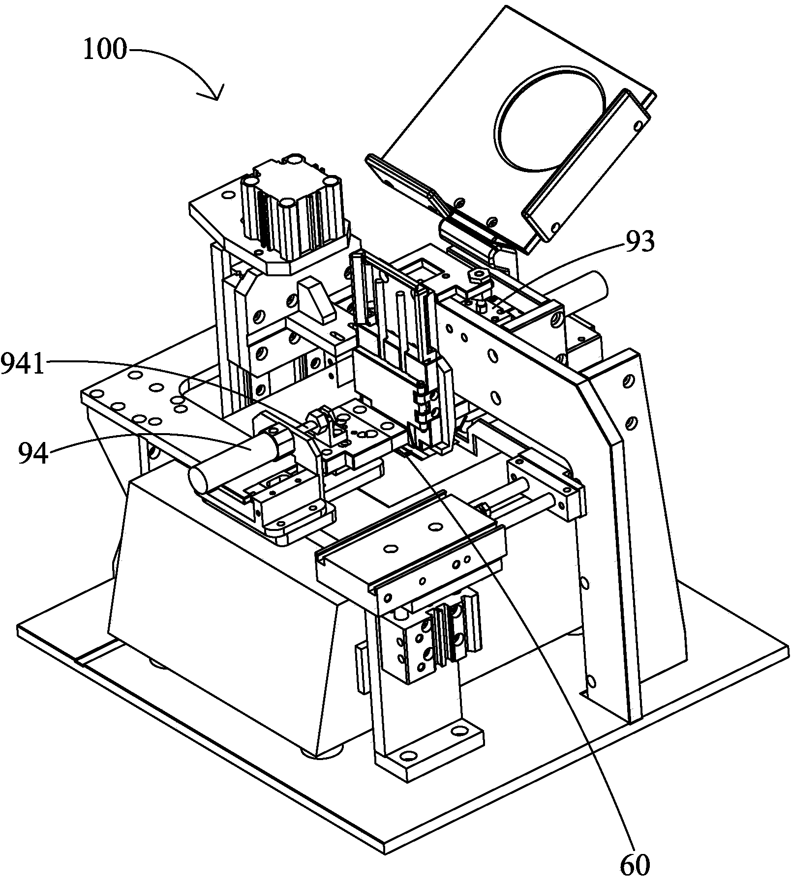
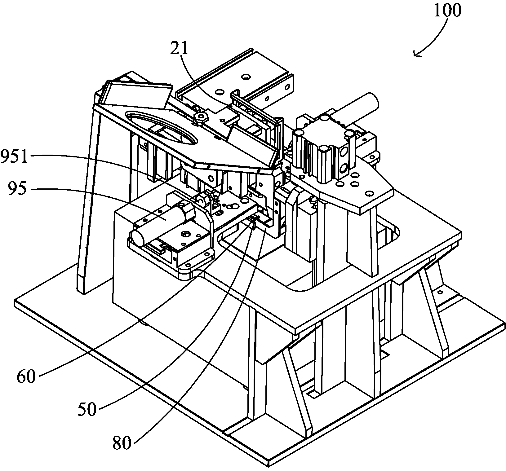
[0021] see Figure 1 to Figure 8 As described above, the weaving tin dipping device 100 of the present invention includes a base 10, a bracket 20, a tray 30, a positioning carrier 40, a tin scraping knife 50, a pair of scraping knitting knives 60 spaced apart from front and back, a tin furnace 70, a tin spoon 80, Several air cylinders and electric control boxes (not shown), the electric control boxes are connected with each air cylinder 91-96, and are used to control the running state of the weaving tin dipping equipment 100.

[0022] Support 20 is installed on the base 10, and each cylinder 91-96 is installed on the support 20, and cylinder 91-96 is provided with six altogether, namely the first, the second, the third, the fourth, the fifth, the sixth cylinder 91, 92, 93, 94, 95, 96, the first cylinder 91 is connected with the tin scraper 40 through a connecting rod 911, which can drive the tin scraper 40 to move back and forth, so that the tin scraper 40 cleans the tin surfa...


PUM


Abstract

The invention relates to a cable weaving tin dipping device which comprises a base, a support, a tray, a location carrier, a tin furnace and a plurality of cylinders. The support is installed on the base, the tin furnace is arranged on the base and used for containing a tin material, the tray is installed on the support and used for placing a cable, the location carrier is located under the tray and used for clamping and fixing the cable, the tail of the cable stretches downwards out of the location carrier, and the weaving portion on the tail is exposed to the outer portion. The device is characterized by further comprising a tin spoon located above the tin furnace and connected with one cylinder, the tin spoon is located in a tin material in the tin furnace, the tin spoon can move upwards out of the tin furnace under the driving of the cylinder, the location carrier is connected with another cylinder, the cylinder can drive the location carrier to move downwards to drive the tail portion of the cable to be immersed into the tin material of the tin spoon and then move upwards out of the tin spoon, the tin spoon contains the tin material of identical quantity every time, and the tin dipping length of the front and the back of the cable is consistent.

Description

technical field [0001] The invention relates to a cable processing device, in particular to a cable braiding and tinning device and method. Background technique [0002] Cable is a commonly used signal transmission line in the electronics industry. It is usually composed of conductors, insulators, braids and jackets. The quality of the cable is directly related to whether the entire electrical equipment can work normally. During the cable processing process, it is necessary to first The outer part of the cable head is stripped, and then the braiding of the cable is tinned, which is convenient for subsequent processing. However, during the tinning process of the cable braiding in the tin furnace, after a period of time, due to the use of tin material, the tin The tin surface of the furnace will drop. If the cable is still lowered into the original height of the tin furnace, the position of the tin material will drop, resulting in inconsistent lengths of tin dipping before and...

Claims


Application Information

Patent Timeline
Patent Type & Authority Applications(China)
IPC IPC(8): B23K1/08B23K3/06
CPCB23K1/08B23K3/0669B23K3/08H01R43/0235
Inventor 周智张军
Owner KUNSHAN XUNTAO PRECISION MACHINERY
Why Eureka
Try Eureka