Bonding method

A technology of lamination and sticking area, applied in the direction of adhesive heating, adhesive, etc., can solve the problems of not being able to fully fit large-size products, poor lamination yield, and inability to rework.

Active Publication Date: 2014-08-27
SUZHOU TONGLI PHOTOELECTRIC CO LTD
View PDF10 Cites 3 Cited by
  • Summary
  • Abstract
  • Description
  • Claims
  • Application Information

AI Technical Summary

Problems solved by technology

The disadvantages of this method are: the production efficiency is average, the bonding yield is poor, generally 75% to 90%, and it cannot be reworked. It is only suitable for the bonding of small and medium-sized products, and cannot meet the needs of full bonding of large-sized products.

Method used


Image

  • Bonding method
  • Bonding method
  • Bonding method

Examples


Embodiment

[0066] Embodiment: a kind of pasting method

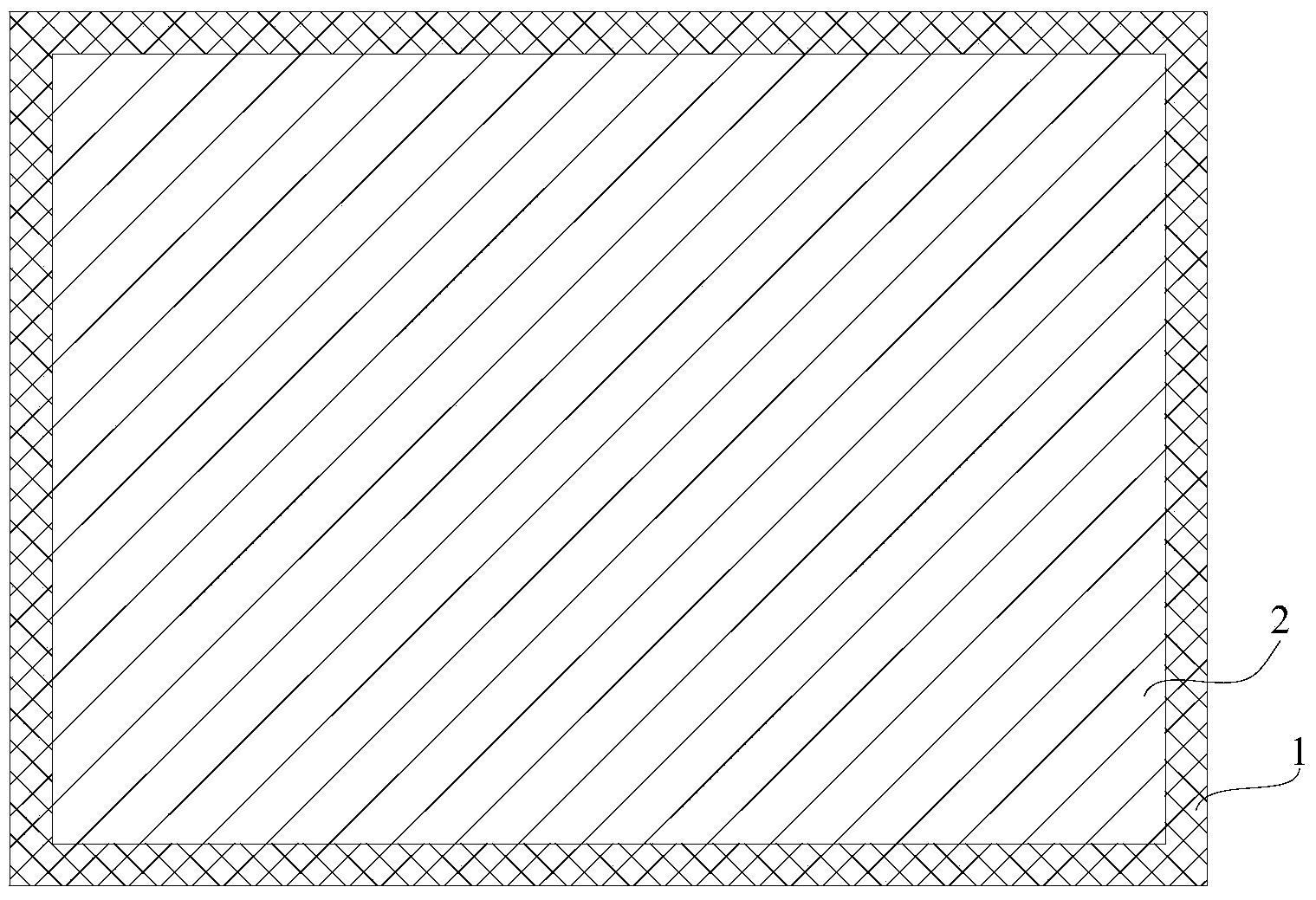
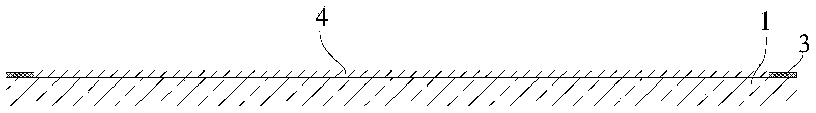
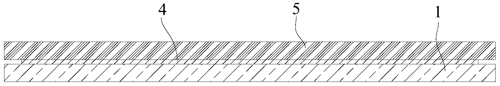
[0067] See attached Figure 1~3 As shown, a bonding method includes the following steps:

[0068] Step 1: Enclose the surface to be glued on the surface of the first component to be bonded 1 (glass cover) with high temperature resistant adhesive tape 3 to form a closed pasting area 2;

[0069] The second step: apply the glue to the sticking area 2 so that in the sticking area 2, the glue is scraped flat, and the excess glue is scraped onto the high temperature resistant adhesive tape, thus forming a A viscose layer 4 with a uniform thickness, and the thickness of the viscose layer 4 is greater than the thickness of the high temperature resistant adhesive tape 3; the glue is made by mixing the A component and the B component according to the mass ratio of 1:1 Obtain; Described A component is made up of the material of blanking weight part:

[0070] Base material 60 parts by weight;

[0071] Catalyst 0.1 part by weight;

[0072]...

Embodiment 2 8

[0107] Embodiments 2-8: a bonding method

[0108] The bonding steps are the same as in Example 1, the difference is the glue: the glue is prepared by mixing component A and component B according to the mass ratio of 1:1.

[0109] The A group batching table of embodiment two~six is ​​as follows:

[0110] Binder catalyst Accessories Embodiment two 85 parts by weight 0.2 parts by weight 25 parts by weight Embodiment Three 95 parts by weight 0.3 parts by weight 15 parts by weight Embodiment Four 90 parts by weight 0.5 parts by weight 20 parts by weight Embodiment five 67 parts by weight 0.1 parts by weight 5 parts by weight Embodiment six 85 parts by weight 0.15 parts by weight 30 parts by weight

[0111] The batching table of B group of embodiment two~six is ​​as follows:

[0112] Binder crosslinking agent Inhibitor Accessories Embodiment two 65 parts by weight 7 parts by weig...

Embodiment 2

[0114] Embodiment 2: The compound conforming to the general formula (1) and the compound conforming to the general formula (2) are mixed according to the mass ratio of 1:1. In general formula (1), R 1 Represents methyl; R 2 , R 3 , R 4 represents a vinyl group; x=20, y=20; the viscosity of the compound conforming to the general formula (1) is 7000 centipoise; in the general formula (2), a is equal to 20, and b is equal to 30.


PUM

PropertyMeasurementUnit
Tensile strengthaaaaaaaaaa
Peel strengthaaaaaaaaaa
Lap shear strengthaaaaaaaaaa

Abstract

The invention discloses a bonding method comprising the following steps of firstly, enclosing on a to-be-glued surface of a first to-be-bonded part by using a high-temperature-resistant adhesive tape to form a closed bonding region; secondly, coating silicone gel to the bonding region to form an adhesive layer with uniform thickness in the bonding region, and enabling the thickness of the adhesive layer to be larger than the thickness of the high-temperature-resistant adhesive tape; thirdly, heating the adhesive layer to solidify a gel solution on the adhesive layer to obtain a solidified adhesive layer; and fourthly, tearing the high-temperature-resistant adhesive tape, and then, bonding a second to-be-bonded part with the first to-be-bonded part. According to the invention, the to-be-glued surface of the first to-be-bonded part is enclosed by using the high-temperature-resistant adhesive tape to form the closed bonding region, so that the adhesive coating range is limited, and furthermore, gel is accurately and rapidly coated.

Description

technical field [0001] The present invention relates to a bonding method, in particular to a full bonding process between a liquid crystal panel or a liquid crystal module and a protective cover, or / and a full bonding process between a protective cover and a touch sensor, or / and a liquid crystal panel Or the full bonding process between the liquid crystal module and the touch sensor. Background technique [0002] Products such as touch screen mobile phones and tablet computers are used more and more widely. The structure of products such as touch-screen mobile phones and tablet computers generally includes a protective cover, a liquid crystal panel (or liquid crystal module) and a touch sensor, and the mutual fixing between them is generally carried out by laminating with a high-transparency adhesive. For example: the publication number is CN102622146, and the Chinese invention patent application titled "A Capacitive Touch Screen and Its Production Method" discloses a capac...

Claims


Application Information

Patent Timeline
IPC IPC(8): C09J5/06C09J183/07C09J183/05
Inventor 石东刘岩
Owner SUZHOU TONGLI PHOTOELECTRIC CO LTD
Why Eureka
Try Eureka