Six-freedom-degree modular pattern telescopic device and manufacturing technology thereof

A telescopic device, degree of freedom technology, applied in the direction of bridge parts, bridges, buildings, etc., can solve the problems of deflection and deformation of the middle beam, shearing of welding joints, damage of weak links, etc.

Active Publication Date: 2014-08-27
HEBEI BAOLI ENG EQUIP GRP CO LTD
View PDF8 Cites 7 Cited by
  • Summary
  • Abstract
  • Description
  • Claims
  • Application Information

AI Technical Summary

Problems solved by technology

[0003] The modular telescopic device is composed of side beams, middle beams, beams and linkage mechanisms. This structure only provides two degrees of freedom, namely, the temperature displacement along the bridge and the deflection deformation of the beam caused by the vehicle, that is, the rotation around the axis of the bridge. During the operation of the bridge, the following defects will occur: the deflection and deformation of the middle girder caused by the vehicle are restricted, and the welds between the hanger and the middle girder, the linkage device and the middle girder will be torn apart after multiple openings; The beam only bears the impact of the vehicle speed with a small weld seam,

Method used


Image

  • Six-freedom-degree modular pattern telescopic device and manufacturing technology thereof
  • Six-freedom-degree modular pattern telescopic device and manufacturing technology thereof
  • Six-freedom-degree modular pattern telescopic device and manufacturing technology thereof

Examples


Embodiment Construction

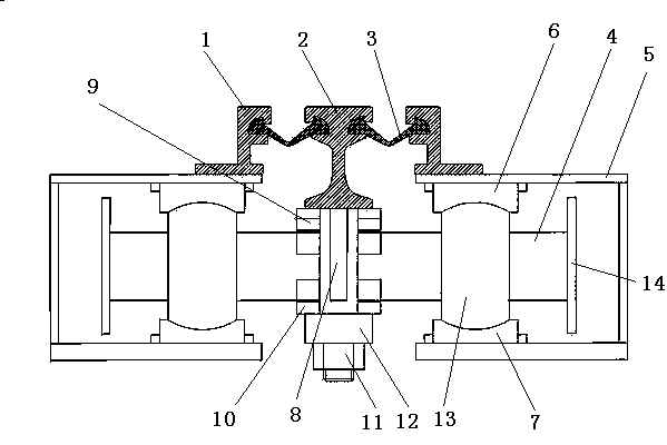
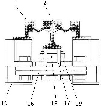
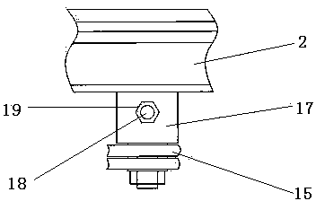
[0039] The structure of a six-degree-of-freedom modular expansion device provided by the present invention will be further described below in conjunction with the accompanying drawings.

[0040] Such as figure 1As shown, a six-degree-of-freedom modular expansion device of the present invention includes a pair of side beam special-shaped steel 1 and a middle beam special-shaped steel 2 arranged between the bridge end expansion joints, and the side beam special-shaped steel 1 and the middle beam special-shaped steel 2 is provided with a waterproof rubber strip 3, and a displacement control box 5 with a supporting beam 4 is provided under the side beam special-shaped steel 1, and the upper side of the supporting beam 4 at the position matching with the side beam special-shaped steel 1 in the displacement control box 5 A side beam compression support 6 is provided, and a side beam pressure bearing support 7 is arranged below, a hanger 8 through which the support beam 4 passes is ...


PUM


Abstract

The invention belongs to the technical field of telescopic devices and discloses a six-freedom-degree modular pattern telescopic device and a manufacturing technology thereof. The telescopic device is mainly characterized in that side beam special-shaped steel, middle beam special-shaped steel, a displacement control box with a supporting horizontal beam, a side beam pressing support and a side beam pressure bearing support and a chain box provided with a transmission chain are included, a hanging frame, a middle beam pressing support and a middle beam pressure bearing support are arranged at the bottom of the middle beam special-shaped steel, the supporting horizontal beam is a solid cylinder or a hollow circular pipe body, the supporting horizontal beam is provided with a drum-shaped multi-direction flexure hinge, the contacting face of the side beam pressing support, the side beam pressure bearing support and the multi-direction flexure hinge is a concave spherical surface, the contacting face of the middle pressing support, the middle pressure bearing support and the supporting horizontal beam is a concave column face, the middle beam special-shaped steel is provided with a middle beam locating block, and a center shaft of a U-shaped locating shaft penetrates through the middle beam locating block. The telescopic device can achieve moving and rotating in a bridge-axis direction, in a direction perpendicular to the bridge-axis direction and in a vertical direction, and the requirements for beam body temperature changing, vehicle rolling, and rotating angles and displacement generated through wind power can be met.

Description

technical field [0001] The invention belongs to the technical field of bridge expansion devices, in particular to a six-degree-of-freedom modular expansion device and a preparation process thereof. Background technique [0002] The currently used bridge expansion devices are more commonly used as modular expansion devices and comb plate expansion devices. [0003] The modular telescopic device is composed of side beams, middle beams, beams and linkage mechanisms. This structure only provides two degrees of freedom, namely, the temperature displacement along the bridge and the deflection deformation of the beam caused by the vehicle, that is, the rotation around the axis of the bridge. During the operation of the bridge, the following defects will occur: the deflection and deformation of the middle girder caused by the vehicle are restricted, and the welds between the hanger and the middle girder, the linkage device and the middle girder will be torn apart after multiple open...

Claims


Application Information

Patent Timeline
IPC IPC(8): E01D19/06
Inventor 刘欣顺高兴丽吴聪利赵九平史洪超吕永胜
Owner HEBEI BAOLI ENG EQUIP GRP CO LTD
Why Eureka
Try Eureka