
Radar time resource joint distribution method related to residence time and re-access interval

A dwell time and joint allocation technology, applied in the direction of radio wave reflection/re-radiation, using re-radiation, measuring devices, etc., can solve the problem of limiting resource optimization effects, unsatisfied revisit time interval, revisit time interval and other resources Problems such as inability to allocate

Active Publication Date: 2014-08-27
XIDIAN UNIV
View PDF8 Cites 18 Cited by
  • Summary
  • Abstract
  • Description
  • Claims
  • Application Information

AI Technical Summary

Problems solved by technology

Although such an independent allocation method has the advantages of fast calculation speed and simple allocation method, on the one hand, the state of the target changes rapidly with time, and resources such as the revisit time interval cannot be dynamically allocated in real time. Scheduling may not be able to meet demand at every moment
On the other hand, phased array radar has multiple controllable resources such as beam dwell time, transmit power, and revisit time interval. Only adjusting the revisit time interval independently will greatly limit the resource optimization effect.
Therefore, the currently adopted phased array radar joint resource scheduling method still has a lot of room for improvement.

Method used


Image

  • Radar time resource joint distribution method related to residence time and re-access interval
  • Radar time resource joint distribution method related to residence time and re-access interval
  • Radar time resource joint distribution method related to residence time and re-access interval

Examples


Embodiment Construction

[0077] The present invention will be further described below in conjunction with accompanying drawing:

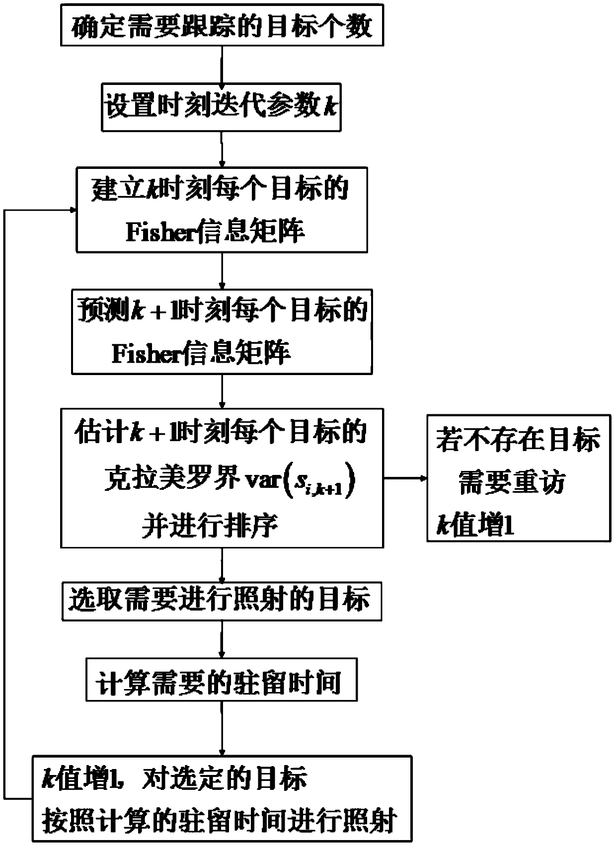
[0078] refer to figure 1 , is a flow chart of the method for jointly allocating radar time resources of dwell time and revisit interval in the present invention. The radar time resource joint allocation method about dwell time and revisit interval includes the following steps:

[0079] Step 1. At the initial moment, the number N of targets that the radar needs to track at the initial moment is determined through the radar's current detection information and previous tracking information. Set 0 time, the 0 time is the initial time, set the time iteration parameter k, k=0,1,2...; when k=0, execute step 2; in the embodiment of the present invention, the radar is phase Control array radar.

[0080] Step 2: Establish the initial Fisher information matrix of each target at time k.

[0081] Its specific sub-steps are:

[0082] (2.1) According to the radar observation data of ...


PUM


Abstract

The invention belongs to the technical field of radar resource utilization, and particularly relates to a radar time resource joint distribution method related to the residence time and the re-access interval. The radar time resource joint distribution method related to the residence time and the re-access interval includes the following steps of firstly, setting the moment k, wherein k equals to 0,1,2...; secondly, establishing a Fisher information matrix of each target at the k moment; thirdly, conducting recurrence to obtain a Fisher information matrix of each target at the k+1 moment; fourthly, calculating the target i, representing the Cramer-Rao bound obtained when radial distance estimation is conducted on the ith target at the k+1 moment as var(si, k+1), setting the error threshold Th1, executing the fifth step if the var(si, k+1), larger than Th1, exists for the corresponding target, and if not, enabling k to be equal to k+1 and repeating the third step, wherein i is larger than or equal to 1 and smaller than or equal to N, and N is the sum of the targets; fifthly, selecting the target irradiated by the radar at the k+1 moment, and obtaining the residence time (please see the specification) of the radar for the j(k)<*>th target at the k+1 moment, wherein the target irradiated by the radar at the k+1 moment is the j(k)<*>th target, and j(k)<*> is larger than or equal to 1 and smaller than or equal to N; sixthly, enabling the value of k to increase by 1 by itself, irradiating the j(k)<*>th target according to the residence time (please see the specification) of the radar for the j(k)<*>th target at the k moment, renewing the Fisher information matrix J[j(k)<*>],k of the j(k)<*>th target at the k moment, and then repeating the third step.

Description

technical field [0001] The invention belongs to the technical field of radar resource utilization, and in particular relates to a joint allocation method of radar time resources related to dwell time and revisit interval, which can be used to improve the tracking performance of phased array radar when performing multi-target tracking. Background technique [0002] Phased array radar is an important development product of the radar system. It breaks the limitations of conventional radar fixed beam dwell time, fixed scanning mode, fixed transmission power and fixed data rate, and has flexible, fast and controllable spatial power of beam scanning. The advantages of allocation and time resource allocation enable the phased array radar to complete the search and track multiple targets at the same time. Target tracking resource management and control functions include revisit interval under target tracking, tracking waveform, determination of beam pointing, and resource allocation...

Claims


Application Information

Patent Timeline
IPC IPC(8): G01S7/02
CPCG01S7/02G01S13/66G01S2013/0245
Inventor 刘宏伟戴奉周秦童严俊坤
Owner XIDIAN UNIV
Learn More