Sound emitter, sound emission device, and electronic apparatus
A sound generator and sound technology, applied in piezoelectric devices/electrostrictive devices, transducer shells/cabinets/supports, circuits, etc., can solve the problems of sound pressure frequency changes, hinder sound quality improvement, etc., to achieve sound quality improvement Effect
- Summary
- Abstract
- Description
- Claims
- Application Information
AI Technical Summary
Problems solved by technology
Method used
Image

Examples
no. 1 Embodiment approach
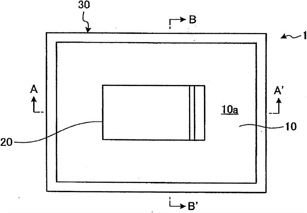
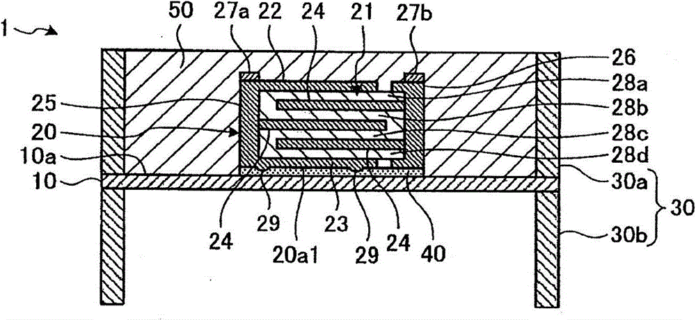
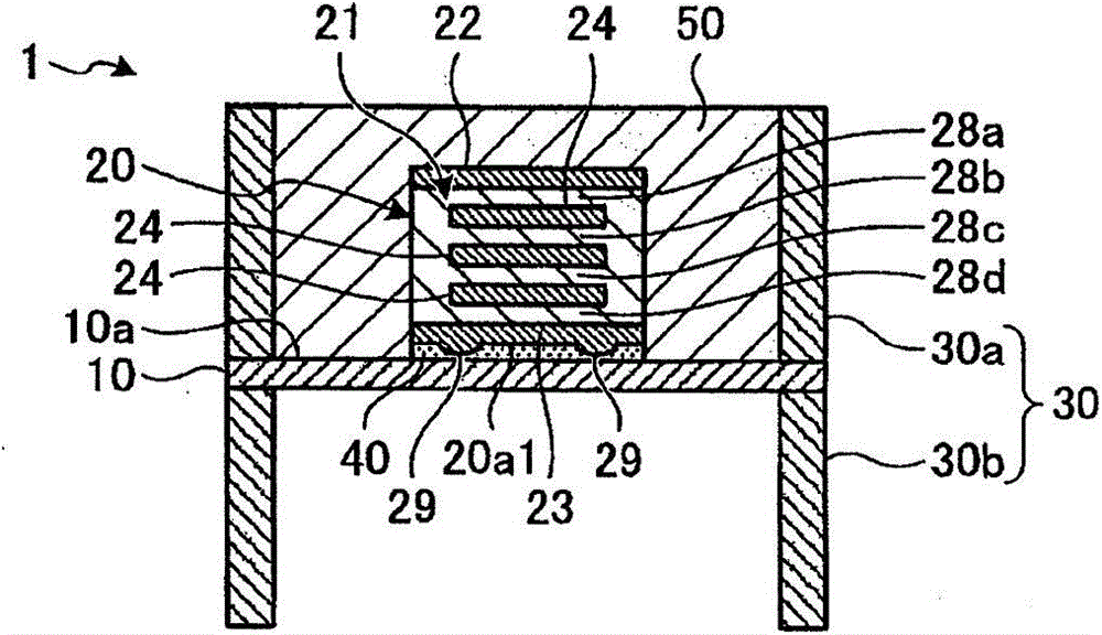
[0033] Figure 1A It is a schematic plan view of the sound generator 1 according to the first embodiment viewed from a direction perpendicular to the main surface of the vibrating body 10, Figure 1B yes Figure 1A The A-A' line sectional view, Figure 1C yes Figure 1A The B-B' line sectional view. In addition, in Figure 1B as well as Figure 1C In , the sound generator 1 is expanded and deformed in the vertical direction for easy understanding.
[0034] Such as Figure 1A ~ Figure 1C As shown, the sound generator 1 according to the first embodiment includes a vibrating body 10 , a piezoelectric vibrating element 20 as an example of an exciter vibrating upon receiving an input of an electric signal, and a housing 30 . Such an acoustic generator 1 is called a so-called piezoelectric speaker, and generates sound pressure by utilizing the resonance phenomenon of the vibrating body 10 itself.
[0035] The vibrating body 10 can be formed of various materials such as resin, m...
no. 2 Embodiment approach
[0073] Figure 9 represents the sound generator 1 according to the second embodiment Figure 1AThe B-B' line section diagram, Figure 10 yes means Figure 9 A schematic diagram of an arrangement example of the recesses in the piezoelectric vibrating element 20 shown. In addition, in Figure 9 In , the sound generator 1 is expanded and deformed in the vertical direction for easy understanding. Also, for Figure 1A ~ Figure 1C The same configurations as those of the first embodiment shown are given the same reference numerals, and description thereof will be omitted.
[0074] Figure 9 , Figure 10 The shown piezoelectric vibrating element 20 has a concave portion 39 opening toward the vibrating body 10 side on the surface on the vibrating body 10 side. Specifically, the piezoelectric vibrating element 20 (vibrator) is provided with a surface electrode layer 23 (first electrode) on the surface side facing the vibrating body 10, and the vibration of the piezoelectric vibra...
no. 3 Embodiment approach
[0081] In each of the configurations described above, the configuration in which either the convex portion 29 or the concave portion 39 is arranged on the surface of the surface electrode layer 23 is shown, but both the convex portion 29 and the concave portion 39 may be arranged. For example, it is also possible to Figure 12 As shown, on the surface of the surface electrode layer 23, the recessed part 39 is arrange|positioned in a part among the outer peripheral part, and the convex part 29 is arrange|positioned in the remaining part.
[0082] Thus, by arranging both the convex portion 29 and the concave portion 39 on the surface of the surface electrode layer 23 , the transmission method of the vibration transmitted from the piezoelectric vibrating element 20 to the vibrating body 10 is further changed. Therefore, in the piezoelectric vibrating element 20 , the resonance frequency is dispersed by the convex portion 29 and the concave portion 39 , and the peak shape of the s...
PUM
 Abstract
Description
Claims
Application Information