
Solar cell panel dust removal device based on RF wireless transmission control

A technology of solar panels and dust removal devices, applied in photovoltaic power generation, electrical components, cleaning with electrostatic methods, etc., can solve the problems of unusable, complex structure, high energy consumption and high cost, and achieve avoiding distance restrictions, flexible adjustment, and control convenient effect

Inactive Publication Date: 2014-09-03
苏州昊枫环保科技有限公司
View PDF6 Cites 0 Cited by
  • Summary
  • Abstract
  • Description
  • Claims
  • Application Information

AI Technical Summary

Problems solved by technology

[0002] The glass plate on the surface of the solar panel is often prone to dust, which will cause a sharp drop in the power generation efficiency of the solar panel and seriously affect the power generation efficiency of the solar power station
At present, the dust removal methods on the surface of solar panels mainly rely on several methods such as wind dust removal, ultrasonic dust removal, and scraper dust removal. The main disadvantages of the above dust removal methods are: the reliability of wind dust removal and scraper dust removal is not high. Short and unusable in harsh environments; the disadvantages of ultrasonic dust removal are high cost and poor ease of use
[0003] The electromagnetic plane dust removal device that has appeared so far uses a dust detection sensor and a pair of electrodes to apply an alternating current to the electrode by detecting the amount of dust, and the dust is removed by electrostatic force; when this dust removal device is used, due to the application of The fixed-size alternating current has poor controllability and cannot be adjusted flexibly, resulting in high energy consumption and cost. The detection accuracy of the dust sensor is not high, and the dust removal operation cannot be accurately controlled, resulting in poor dust removal effect

Method used


Image

  • Solar cell panel dust removal device based on RF wireless transmission control
  • Solar cell panel dust removal device based on RF wireless transmission control

Examples


Embodiment Construction

[0011] The specific implementation manner of the present invention will be described below in conjunction with the accompanying drawings.

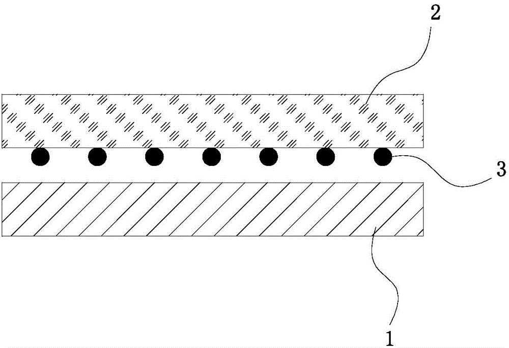
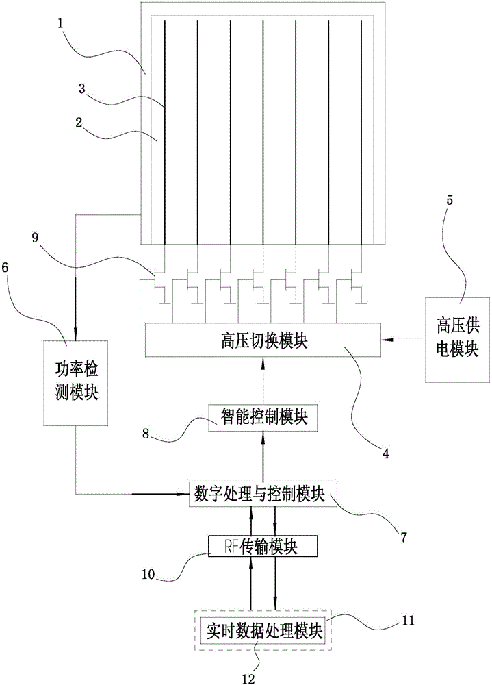
[0012] See figure 1 and figure 2 , the present invention includes a solar cell panel 1 and a glass protective layer 2, the lower surface of the glass protective layer 2 is equipped with a plurality of parallel electrodes 3, the ends of the electrodes 3 are respectively connected to a high-voltage switch 9, and the high-voltage switch 9 is electrically connected to a high-voltage switching module 4 , the high-voltage switching module 4 is powered by the high-voltage power supply module 5, and the high-voltage switching module 4 alternately applies high voltage to the electrodes 3, and a fluctuating electrostatic field is generated between the electrodes 3, and the dust on the glass protective layer 2 floats after being polarized by the electrostatic field and Fluctuation falls off; the output end of the solar panel 1 is connected with a p...


PUM


Abstract

The invention relates to a solar cell panel dust removal device based on RF wireless transmission control. The solar cell panel dust removal device comprises a solar cell panel and a glass protective layer. The lower surface of the glass protective layer is provided with multiple parallel electrodes, the ends of the electrodes are connected with high-voltage switches which are electrically connected with a high-voltage switching module, and the high-voltage switching module supplies electric power through a high-voltage power supply module. The output end of the solar cell panel is connected with a power detection module which is connected with a digital processing and control module. The digital processing and control module is connected with the high-voltage switching module through an intelligent control module and connected with a host through an RF transmission module. A real-time data processing module is arranged in the host. The solar cell panel dust removal device has the advantages of being convenient to control, high in controllability, flexible in adjustment and low in cost.

Description

technical field [0001] The invention relates to a solar battery panel, in particular to a dust removal device for a solar battery panel. Background technique [0002] The glass plate on the surface of the solar panel is often prone to dust accumulation, which will lead to a sharp drop in the power generation efficiency of the solar panel and seriously affect the power generation efficiency of the solar power station. At present, the dust removal methods on the surface of solar panels mainly rely on several methods such as wind dust removal, ultrasonic dust removal, and scraper dust removal. The main disadvantages of the above dust removal methods are: the reliability of wind dust removal and scraper dust removal is not high. It is short and cannot be used in harsh environments; the disadvantages of ultrasonic dust removal are high cost and poor usability. [0003] The electromagnetic plane dust removal device that has appeared so far uses a dust detection sensor and a pair ...

Claims


Application Information

Patent Timeline
Patent Type & Authority Applications(China)
IPC IPC(8): B08B6/00B08B13/00H02S40/10
CPCB08B6/00Y02E10/50
Inventor 不公告发明人
Owner 苏州昊枫环保科技有限公司
Learn More