Double-clamping flat-pushing non-gravity-type electro-hydraulic vehicle retarder

A double-clamp flat-push, non-gravity technology, applied in track brakes, railway car body parts, transportation and packaging, etc., can solve problems affecting normal marshalling operations, large changes in braking force, and unstable braking friction , to achieve the effect of low service life, low working pressure and low power

Active Publication Date: 2014-09-03
TIANJIN RAILWAY SIGNAL
View PDF5 Cites 9 Cited by
  • Summary
  • Abstract
  • Description
  • Claims
  • Application Information

AI Technical Summary

Problems solved by technology

However, the braking force varies greatly and the braking noise is large. Pneumatic non-gravity reducers also have such problems, especially gravity reducers, which are easy to cause light vehicles to jump, and the fatigue strength of structural parts is related to the weight of the vehicle. Limit vehicle heavy load development
With the development of heavy load, there will be breakage of main parts and components, which will affect the normal marshalling operation
In addition, the parts on which the brake splint is installed in the existing clamp-type reducer are all rotating motions. With the difference in the opening of the brake splint or the width of the wheel rim, the contact between the brake splint and the wheel rim is often a line contact, and the braking friction is unstable. The precision of vehicle control is low, and the actual control process relies on frequent braking to improve the precision of vehicle control, resulting in high energy consumption

Method used


Image

  • Double-clamping flat-pushing non-gravity-type electro-hydraulic vehicle retarder
  • Double-clamping flat-pushing non-gravity-type electro-hydraulic vehicle retarder
  • Double-clamping flat-pushing non-gravity-type electro-hydraulic vehicle retarder

Examples


Embodiment Construction

[0026] Specific embodiments of the present invention will be described in detail below in conjunction with the accompanying drawings.

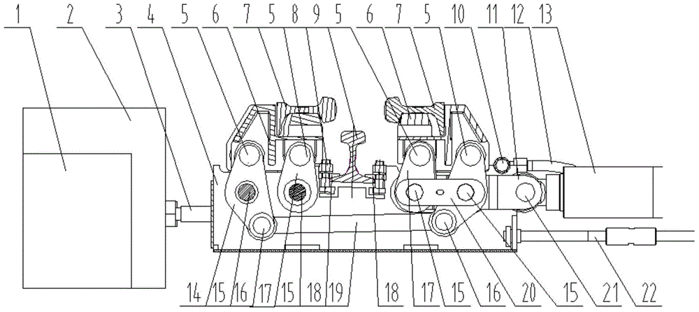
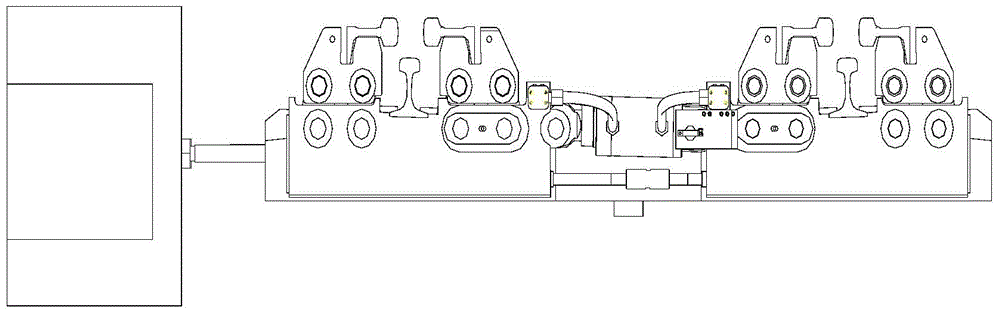
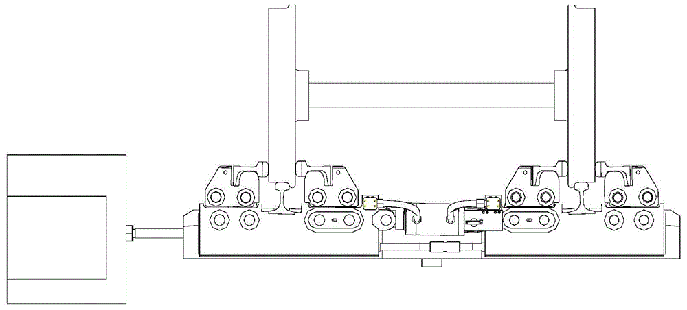
[0027] Such as Figure 1~4 As shown, a double-clamp flat-push non-gravity electro-hydraulic vehicle speed reducer includes a speed reducer installed on the basic rail 9 and a brake splint 7, and the speed reducer is a double-clip flat-push brake mechanism, including two complete For the same brake mechanism unit, a double-rod cylinder 13 is arranged between the two brake mechanism units, and is symmetrical about the double-rod cylinder 13 . The brake pads 7 are respectively in contact with the side surfaces of the wheels to achieve the purpose of braking. The oil cylinder 13 is connected with the hydraulic station 2 and the electric control box 1 . The hydraulic station 2 is connected with the oil cylinder 13 through the oil pipe, and the oil pipe includes the main rubber hose 3, the oil distribution pipe 10, and the rubber hose 12 connected...


PUM


Abstract

The invention provides a double-clamping flat-pushing non-gravity type electro-hydraulic vehicle retarder. The double-clamping flat-pushing non-gravity-type electro-hydraulic vehicle retarder comprises a vehicle retarder body arranged on a basic rail and a braking clamping plate, wherein the retarder body is a double-clamping flat pushing braking mechanism and comprises two braking mechanism units which are completely same, an oil cylinder is arranged between the two braking mechanism units, and the two braking mechanism units are symmetrical about the oil cylinder. The double-clamping flat pushing non-gravity-type electro-hydraulic vehicle retarder provided by the invention has the advantages and positive effects that the vehicle retarder body is in an electro-hydraulic non-gravity type, the hydraumatic movement is sensitive, braking force is adjustable, the brake and the gravity are not related, a problem that the clamping of a light vehicle is missed so as to derail is solved, and the vehicle retarder is suitable for heavy load development; the retarder is in a flat-pushing type, a braking clamping plate and a side surface of a wheel are in plane contact, the abrasion of a braking surface is reduced, the stability of the braking force is improved, and the control vehicle precision is high, the retarder only uses one oil cylinder, the oil cylinder is horizontally installed in middle of a station track, the cost is low, and the change is convenient.

Description

technical field [0001] The invention belongs to the field of railway equipment, in particular to a double-clamp flat push non-gravity electro-hydraulic vehicle reducer. Background technique [0002] At present, the domestic hump vehicle reducer has pneumatic gravity clamp type, hydraulic gravity clamp type, electric gravity clamp type, electro-hydraulic inner support type, pneumatic non-gravity clamp type, but there is no electro-hydraulic non-gravity double clamp flat push type . Gravity vehicle reducers are mainly pneumatic, and electro-hydraulic is rarely used. The non-gravity pneumatic is mainly used in the interval position, and the electro-hydraulic internal support type reducer is mainly suitable for the purpose of the small hump marshalling field. Pneumatic gravity reducer has low failure points and less maintenance. Even if compressed air is used, it will not pollute the environment. It is the main speed control equipment for hump marshalling stations in China. H...

Claims


Application Information

Patent Timeline
Patent Type & Authority Applications(China)
IPC IPC(8): B61K7/08B61K7/04
Inventor 寇建设樊胜秋杨一伟张军史国珍刘永胜许世雄
Owner TIANJIN RAILWAY SIGNAL
Why Eureka
Try Eureka