Edge locking clamp for rolling of film rolls

A gripper and edge locking technology, applied in the direction of winding strip, thin material processing, transportation and packaging, etc., can solve the problems of film edge wrinkling, normal processing influence, and unsatisfactory film roll surface flatness, etc. Achieve the effect of avoiding running edge wrinkling and ensuring flatness

Inactive Publication Date: 2014-09-03
永新股份(黄山)包装有限公司
View PDF8 Cites 4 Cited by
  • Summary
  • Abstract
  • Description
  • Claims
  • Application Information

AI Technical Summary

Problems solved by technology

The current film production is all produced by extrusion casting, and then the rolling purpose is realized by friction rollers; the above-mentioned friction winding operation, due to the high speed of film travel (its travel speed can reach 600m / min), which is very sensitive to the beating and straightness of the rewinding roller, the air shaft, and the surface of the paper tube, and often occurs due to the beating of the above parts, and the phenomenon of wrinkling on the running side of the film when the film is running, resulting in that after the rewinding is completed The surface flatness of the film roll is not ideal, which will eventually have a great impact on the normal processing of the downstream process

Method used


Image

  • Edge locking clamp for rolling of film rolls
  • Edge locking clamp for rolling of film rolls

Examples


Embodiment Construction

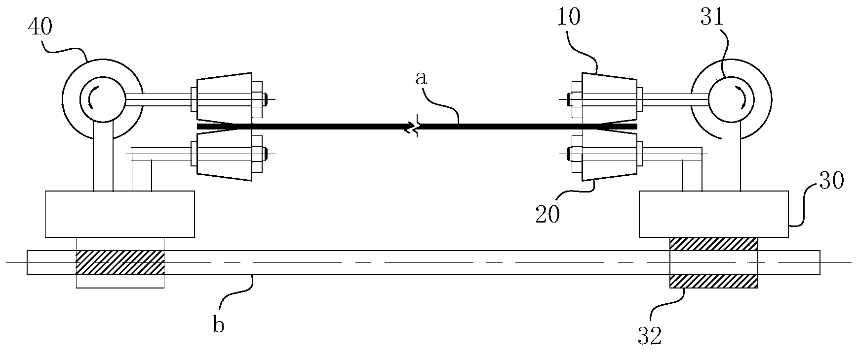
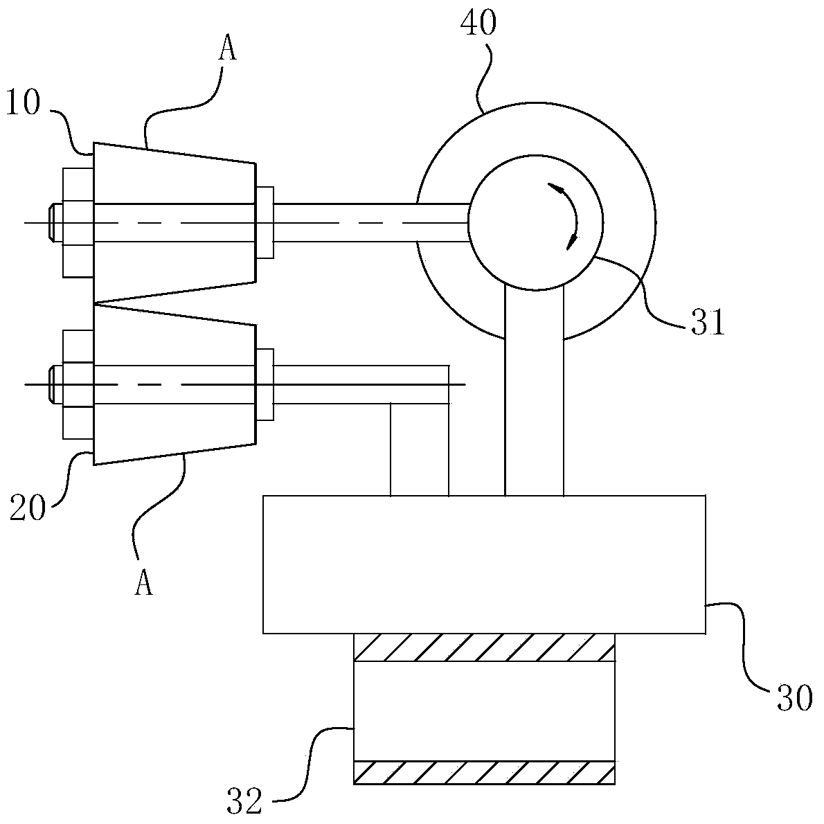
[0019] For ease of understanding, combined here Figure 1-2 Concrete structure of the present invention and working method thereof are described as follows:

[0020] Concrete structure of the present invention, as Figure 1-2 As shown, it includes pinch rollers arranged on the film travel path on the friction roller, and the pinch rollers are arranged symmetrically with the center line a of the film being pinched as the symmetry line. The clamping roller includes an upper roller 10 and a lower roller 20, and the upper roller 10 and the lower roller 20 are in the shape of a conical roller with the same shape; due to the conical structure of the rollers, the film is clamped and rotated between the two rollers. , the tapered surface A on the clamping roller will always apply to the clamped film a to clamp the side force; under the action of the clamped side force, the clamped film a is tensioned and always Traveling and conveying in a flat state, the phenomenon of wrinkling and...


PUM


Abstract

The invention belongs to the field of film roll rolling devices and particularly relates to an edge locking clamp for rolling of film rollers. The edge locking clamp comprises upper roller wheels and lower roller wheels which form clamping rollers, and the matched clamping gaps of the upper roller wheels and the lower roller wheels form a gap for moving of a clamped thin film. The roller faces, in contact with the clamped thin film, on the upper roller wheels and/or the lower roller wheels are provided with conical faces. The axes of the conical faces are coaxial with the axes of the corresponding roller wheels of the conical faces, and the small ends of the conical faces point to the direction in which the clamped thin film is to be stretched and are arranged in the direction in which the clamped film is to be stretched. Each clamping roller formed through matching of the corresponding upper roller wheel and the corresponding lower roller wheel forms a set, at least two sets of the clamping rollers are arranged at the two sides of the clamped thin film respectively. According to the edge locking clamp, the clamping rollers with the conical faces are additionally arranged, so that the function of edge stabilizing and the function of edge locking in the moving process of the thin film are achieved by depending on the clamping and stretching force on the side edge of the thin film by the conical faces on the clamping rollers, the thin film is stretched tightly, flatness of stretching in the moving process of the thin film is finally ensured, and the edge deviation and corrugation phenomena of the thin film in the rolling process are improved and even avoided.

Description

technical field [0001] The invention belongs to the field of film roll winding equipment, and in particular relates to an overlock clamper for film roll winding. Background technique [0002] Films are widely used in every corner of life and production. The current film production is all produced by extrusion casting, and then the rolling purpose is realized by friction rollers; the above-mentioned friction winding operation, due to the high speed of film travel (its travel speed can reach 600m / min), which is very sensitive to the beating and straightness of the rewinding roller, the air shaft, and the surface of the paper tube, and often occurs due to the beating of the above parts, and the phenomenon of wrinkling on the running side of the film when the film is running, resulting in that after the rewinding is completed The surface flatness of the film roll is not ideal, which will eventually have a great impact on the normal processing of the downstream process. Conte...

Claims


Application Information

Patent Timeline
Patent Type & Authority Applications(China)
IPC IPC(8): B65H23/34B65H23/26
Inventor 叶青松朱小华陈付兵谢永胜陈旭
Owner 永新股份(黄山)包装有限公司
Why Eureka
Try Eureka