Locking structure of slotted nut

A technology for locking structures and nuts, which is applied in the direction of nuts, threaded fasteners, locking fasteners, etc., which can solve the problem of lack of locking effect, unfixed size of channel nuts, and small size of locking clips that cannot be fixed and other problems to achieve the effect of avoiding insufficient locking, simple locking method and preventing loosening

Inactive Publication Date: 2019-06-07
TIANJIN TEEK TRANSMISSION
View PDF7 Cites 1 Cited by
  • Summary
  • Abstract
  • Description
  • Claims
  • Application Information

AI Technical Summary

Problems solved by technology

[0003] In order to prevent the channel nut from loosening during use, the channel nut is generally fixed with a locking clip to prevent the channel nut from

Method used


Image

  • Locking structure of slotted nut
  • Locking structure of slotted nut
  • Locking structure of slotted nut

Examples


specific Embodiment 1

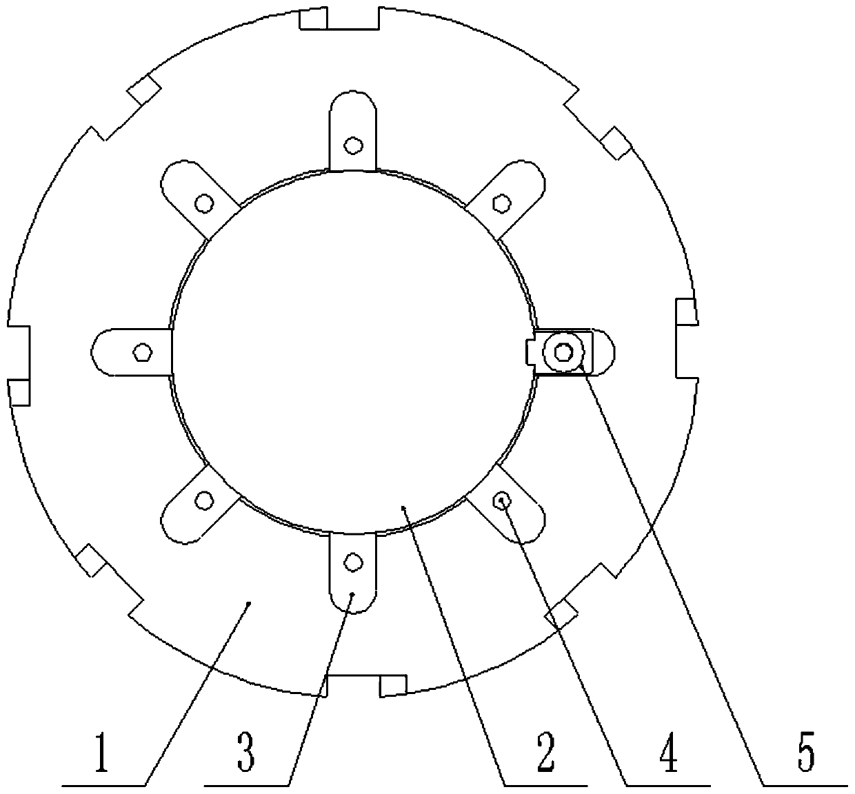
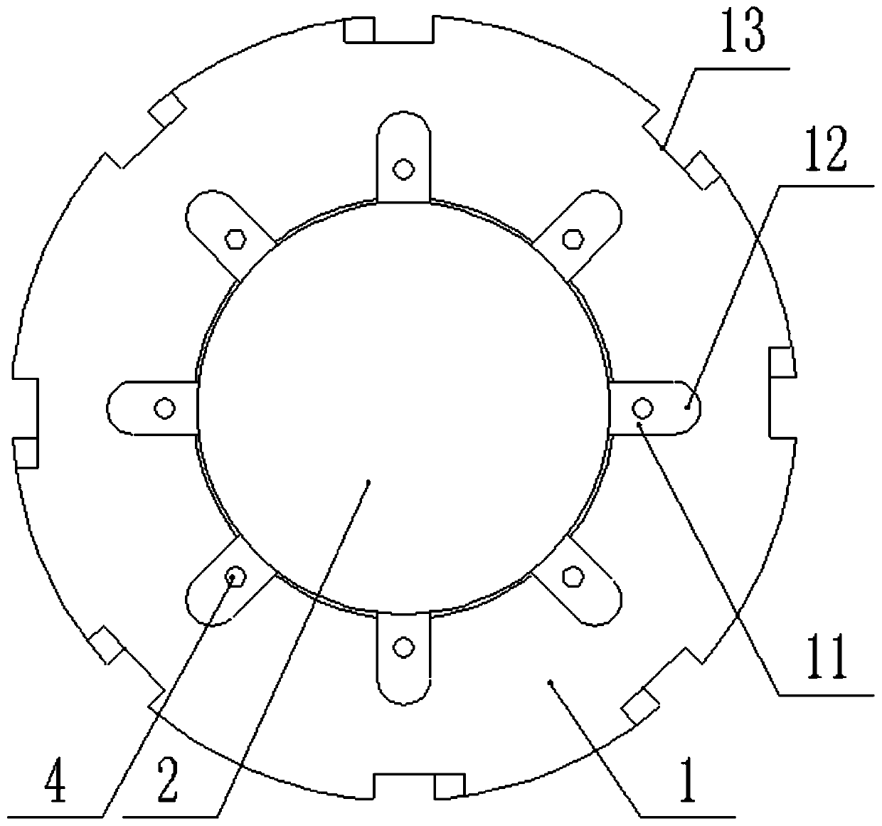
[0023] Such as Figure 1 to Figure 5 As shown,

[0024] A locking structure for a trough nut includes a trough nut 1, a threaded hole 2 penetrates through the center of the trough nut 1, a connecting shaft is screwed in the threaded hole 2, and a locking vertical is provided on the connecting shaft. A groove, the upper surface of the groove nut 1 is provided with a number of grooves 3 along the outer edge of the threaded hole 2, one end of the groove 3 is communicated with the threaded hole 2, and a connecting threaded hole 4 is provided in the groove 3 , The groove 3 corresponding to the vertical slot on the connecting shaft is provided with a locking piece 5, and the locking piece 5 is provided with a counterbore 6 corresponding to the connecting threaded hole 4, and the counterbore 6, connecting A countersunk screw 7 is screwed into the threaded hole 4, and a side surface of the locking piece 5 facing the threaded hole 2 is provided with a protruding portion 8 which is clampe...

specific Embodiment 2

[0026] Such as Figure 1 to Figure 5 As shown,

[0027] A locking structure for a trough nut includes a trough nut 1, a threaded hole 2 penetrates through the center of the trough nut 1, a connecting shaft is screwed in the threaded hole 2, and a locking vertical is provided on the connecting shaft. A groove, the upper surface of the groove nut 1 is provided with a number of grooves 3 along the outer edge of the threaded hole 2, one end of the groove 3 is communicated with the threaded hole 2, and a connecting threaded hole 4 is provided in the groove 3 , The groove 3 corresponding to the vertical slot on the connecting shaft is provided with a locking piece 5, and the locking piece 5 is provided with a countersunk hole 6 corresponding to the connecting threaded hole 4, and the counterbore 6, connecting A countersunk screw 7 is screwed into the threaded hole 4, and a side surface of the locking piece 5 facing the threaded hole 2 is provided with a protruding portion 8 which is c...

specific Embodiment 3

[0030] Such as Figure 1 to Figure 5 As shown,

[0031] A locking structure for a trough nut includes a trough nut 1, a threaded hole 2 penetrates through the center of the trough nut 1, a connecting shaft is screwed in the threaded hole 2, and a locking vertical is provided on the connecting shaft. A groove, the upper surface of the groove nut 1 is provided with a number of grooves 3 along the outer edge of the threaded hole 2, one end of the groove 3 is communicated with the threaded hole 2, and a connecting threaded hole 4 is provided in the groove 3 , The groove 3 corresponding to the vertical slot on the connecting shaft is provided with a locking piece 5, and the locking piece 5 is provided with a counterbore 6 corresponding to the connecting threaded hole 4, and the counterbore 6, connecting A countersunk screw 7 is screwed into the threaded hole 4, and a side surface of the locking piece 5 facing the threaded hole 2 is provided with a protruding portion 8 which is clampe...


PUM


Abstract

The invention relates to a locking structure of a slotted nut. The locking structure comprises the slotted nut, wherein a threaded hole penetrates through the center of the slotted nut, a connecting shaft is screwed in the threaded hole, a clamping vertical groove is formed in the connecting shaft, a plurality of grooves are formed in the upper surface of the slotted nut along the circumference ofthe outer edge of the threaded hole, one end of the grooves communicates with the threaded hole, connecting threaded holes are formed in the grooves, a locking piece is arranged in the groove which corresponds to the clamping vertical groove in the connecting shaft, a counterbore is formed in the locking piece in the mode of corresponding to the connecting threaded hole, countersunk rivets are screwed in the counterbore and the connecting threaded hole, a projecting part is arranged on one side surface, which faces the threaded hole, of the locking piece, and the projecting part is clamped inthe clamping vertical groove in the connecting shaft. According to the locking structure, the slotted nut can be effectively locked, and the slotted nut can be effectively prevented from loosing; compared with other locking modes of the slotted nut, the locking structure has the advantages of simplicity, convenience and simplicity in matching and processing, and the phenomenon of improper lockingdue to the size of a general locking clamp is avoided.

Description

Technical field [0001] The invention relates to the field of locking equipment of mechanical technology, in particular to a locking structure of a groove nut. Background technique [0002] Groove nut is to machine the groove above the nut. It is used in conjunction with a bolt with a hole in the screw and a split pin to prevent the bolt from rotating relative to the nut. [0003] In order to prevent the trough nut from loosening during use, a locking clip is generally used to fix the trough nut to prevent the trough nut from loosening, but the size of the trough nut is not fixed, and sometimes the size of the locking clip is too small. Fixed, no locking effect. Summary of the invention [0004] The present invention aims to solve the shortcomings of the prior art, and provides a groove nut locking structure, which can effectively lock groove nuts of different types and sizes, and avoids the general locking clamp from being locked due to size reasons. Phenomenon in place. [0005] ...

Claims


Application Information

Patent Timeline
IPC IPC(8): F16B37/00F16B39/08
Inventor 廖明建王培
Owner TIANJIN TEEK TRANSMISSION
Why Eureka
Try Eureka