

Water-gas separation device for vacuum pumping of suction machine
A water-gas separation and suction machine technology, applied in separation methods, dispersed particle separation, mechanical equipment, etc., can solve problems such as inability to clean water-gas separation and difficult water discharge
- Summary
- Abstract
- Description
- Claims
- Application Information
AI Technical Summary
Problems solved by technology
Method used
Image

Examples
Embodiment 1
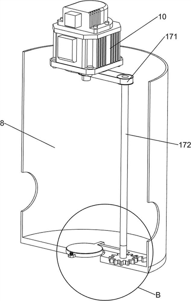
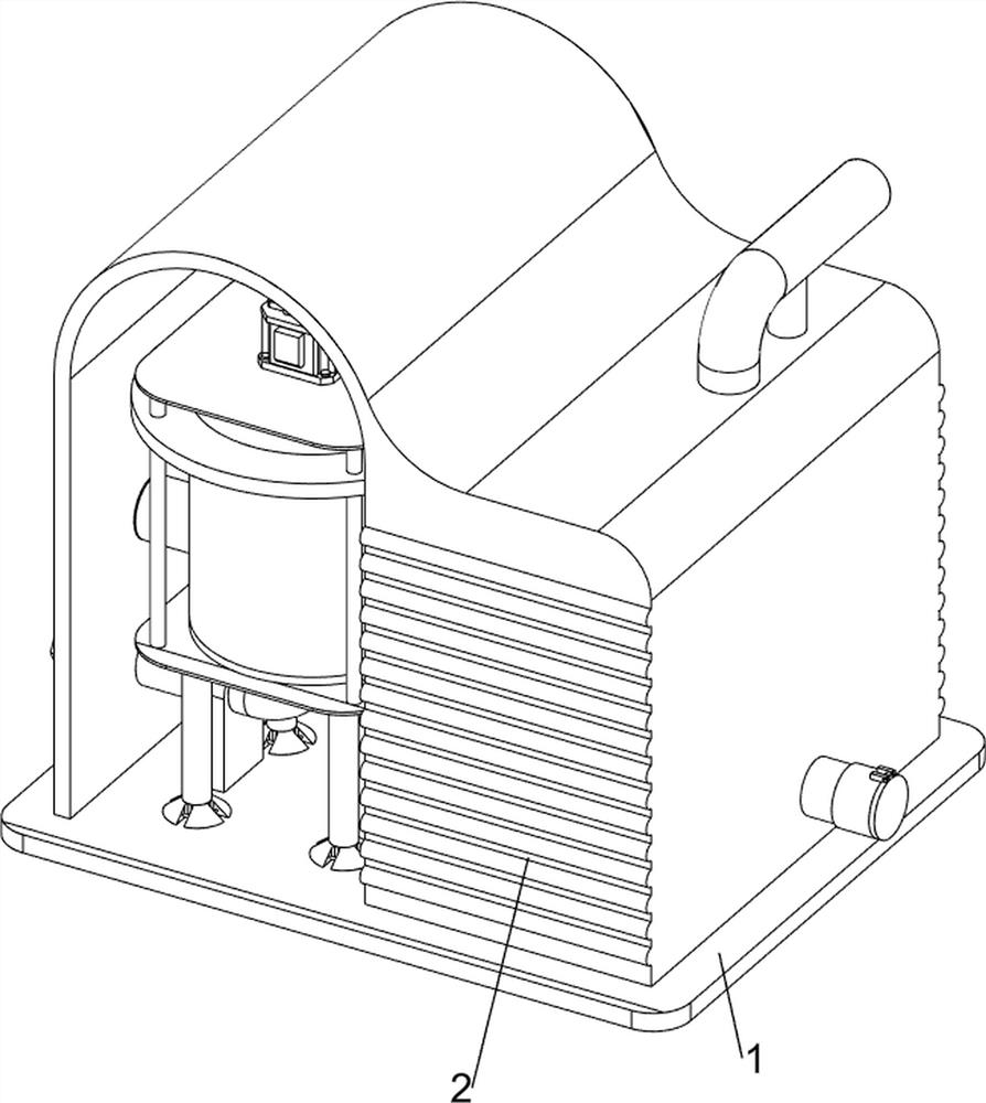
[0090] A kind of suction machine vacuumizes water-air separation device, such as Figure 1-9 As shown, it includes a first bottom plate 1, a first shell 2, a first fixed block 3, a first drain pipe 4, a support foot 5, a first-stage separation bottom plate 6, an inclined plate 7, a first-stage separation shell 8, a first-stage separation Separate the upper fixed plate 9, the motor 10, the impeller 11, the second fixed block 12, the first air intake pipe 13, the suction pipe 14, the suction machine 15, the secondary separation mechanism 16 and the drainage mechanism 17, and the top of the first base plate 1 is provided with There is a first shell 2, a first fixed block 3 is provided on the left front side of the top of the first bottom plate 1, and a first drainage pipe 4 is arranged in the upper part of the first fixed block 3, and the left and right parts on the left front side of the top of the first bottom plate 1 are both front and rear symmetrical There are supporting fee...
Embodiment 2
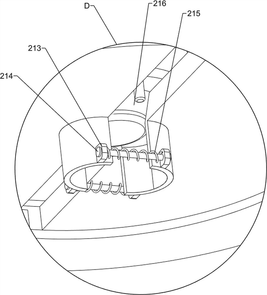
[0097] On the basis of Example 1, such as figure 2 , image 3 , Figure 10-14 As shown, a locking mechanism 18 is also included, and the locking mechanism 18 includes a block 181, a compression spring 182, a fourth fixed block 183, a second fixed rod 184 and a driving rod 185, and the right part of the inner bottom of the primary separation shell 8 The rear side is provided with a fourth fixed block 183, and the fourth fixed block 183 is slidably provided with a block 181. The block 181 cooperates with the first tooth bar 174. A compression spring 182 is wound around the front of the block 181, and the compression spring 182 has two end is connected with clamping block 181 and the 4th fixed block 183 respectively, and the rear side of the right part of the inner bottom of the primary separation housing 8 is rotated to be provided with a driving rod 185, and the driving rod 185 is positioned at the rear of the 4th fixing block 183, and the rear side of the clamping block 181 ...
PUM
 Abstract
Description
Claims
Application Information