
Sliding sleeve screw removing robot

A robot and screw technology, applied in metal processing, metal processing equipment, manufacturing tools, etc., can solve the problem that the screw thread cannot be rotated, and achieve the effect of ensuring safety and stability

Inactive Publication Date: 2021-03-09
冯民荣
View PDF5 Cites 1 Cited by
  • Summary
  • Abstract
  • Description
  • Claims
  • Application Information

AI Technical Summary

Problems solved by technology

[0003] In view of the above problems, the present invention provides a robot for unscrewing the sliding sleeve, which solves the problem that the sliding wire at the screw head cannot be rotated

Method used


Image

  • Sliding sleeve screw removing robot
  • Sliding sleeve screw removing robot
  • Sliding sleeve screw removing robot

Examples


Embodiment

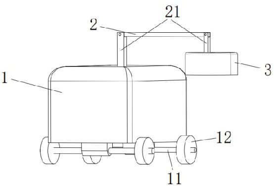
[0028] Such as Figure 1-Figure 7 As shown, a sliding sleeve screw robot is characterized in that it includes a power box 1, a positioning rod 2 and a set-releasing assembly 3, and both ends of the positioning rod 2 are provided with struts 21, and the two struts 21 are respectively Rotately connected with the power box 1 and the release assembly 3, the support rod 21 can be rotated and aligned according to the specific detailed position of the sliding sleeve screw;

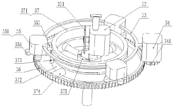
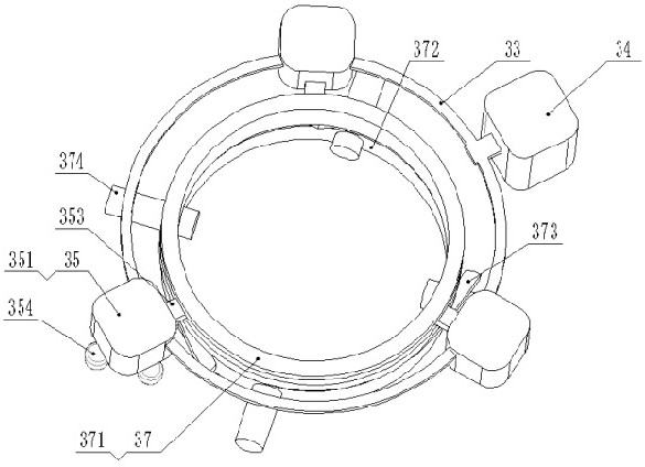
[0029] The unpacking assembly 3 includes a bottomless shell 31, a grinding motor 32, a support ring 33, a torque motor 34, an impact assembly 35, an annular guide rail 36, and a positioning ring 37; the grinding motor 32 is fixedly welded to the top in the shell 31, and the grinding motor 32 A polishing sheet 321 is installed on the top, and the polishing sheet 321 is a circular wheel shape, and the grinding direction is vertically downward with respect to the adjustment rod 2; The motor 34 is fixedly connected ...


PUM


Abstract

The invention discloses a sliding sleeve screw removing robot. The robot is characterized by comprising a power box, a position adjusting rod and a sleeve removing component, wherein the two ends of the position adjusting rod are connected to the power box and the sleeve removing component respectively; the sleeve removing component comprises a bottomless shell, a grinding motor, a support ring, atorsion motor, an impact component, an annular guide rail and a positioning ring, a grinding piece is arranged on the grinding motor, and the grinding motor is connected to the top in the shell; thetorsion motor is connected to the support ring, and a driving wheel is arranged on an output shaft of the torsion motor; gear teeth meshed with the driving wheel are arranged at the outer side of theguide rail; the positioning ring comprises an upper positioning ring and a lower positioning ring; and the lower positioning ring is provided with four through holes, the four through holes equally divide the lower positioning ring into four parts, a telescopic rod is inserted into each through hole, the end, away from the center of the lower positioning ring, of each telescopic rod is connected to the inner side of the guide rail, a plum blossom locking block is arranged at the other end of each telescopic rod, and an anticlockwise inclined groove is arranged in the inner side of each plum blossom locking block. The robot solves the problem that a screw head slips and cannot rotate.

Description

technical field [0001] The invention relates to the technical field of dismantling devices, in particular to a robot for unscrewing slip sleeve screws. Background technique [0002] Screws are widely used, ranging from small hardware, electronic products, electrical products and mechanical equipment products, to large automobiles, ships and aircraft artillery. However, after the screw is disassembled N times, the teeth will slowly slip, causing the head to slip, making it difficult to disassemble and take out in the future. Contents of the invention [0003] In view of the above problems, the present invention provides a robot for unscrewing slip sleeves, which solves the problem that the slip wire at the head of the screw cannot be rotated. [0004] The technical solution used in the present invention is: a sliding sleeve screw robot, which is characterized in that it includes a power box, an adjustment rod and an unscrew assembly, and the two ends of the adjustment rod ...

Claims


Application Information

Patent Timeline
Patent Type & Authority Applications(China)
IPC IPC(8): B23G9/00B23P19/06
CPCB23G9/002B23P19/06
Inventor 冯民荣
Owner 冯民荣
Learn More