
Generator set applicable to low-speed wind power and high-speed wind power

A wind power generator, low-speed technology, applied in the direction of wind power generator components, wind power motor combination, wind power engine, etc., can solve the problem of inability to use wind power resources, achieve the effect of improving the utilization effect, reducing the number of conversions, and prolonging the service life

Active Publication Date: 2014-09-03
HARBIN ENG UNIV
View PDF8 Cites 0 Cited by
  • Summary
  • Abstract
  • Description
  • Claims
  • Application Information

AI Technical Summary

Problems solved by technology

This patent protects wind power generators and wind turbines very well, but after the generators stop running, they cannot use wind resources at high wind speeds
The patent application number is 201120521817.5, and the utility model patent named "Wind Power Generator with Horizontal Axis and Multiple Wind Wheels on Pull Wire Frame", and the utility model patent in 201120115038.5, named "High-speed Wind Power Generator with Multiple Wind Wheels with Horizontal Axis" are not applicable to high-speed wind turbines. wind speed condition

Method used


Image

  • Generator set applicable to low-speed wind power and high-speed wind power
  • Generator set applicable to low-speed wind power and high-speed wind power
  • Generator set applicable to low-speed wind power and high-speed wind power

Examples


Embodiment Construction

[0014] The present invention is described in more detail below in conjunction with accompanying drawing example:

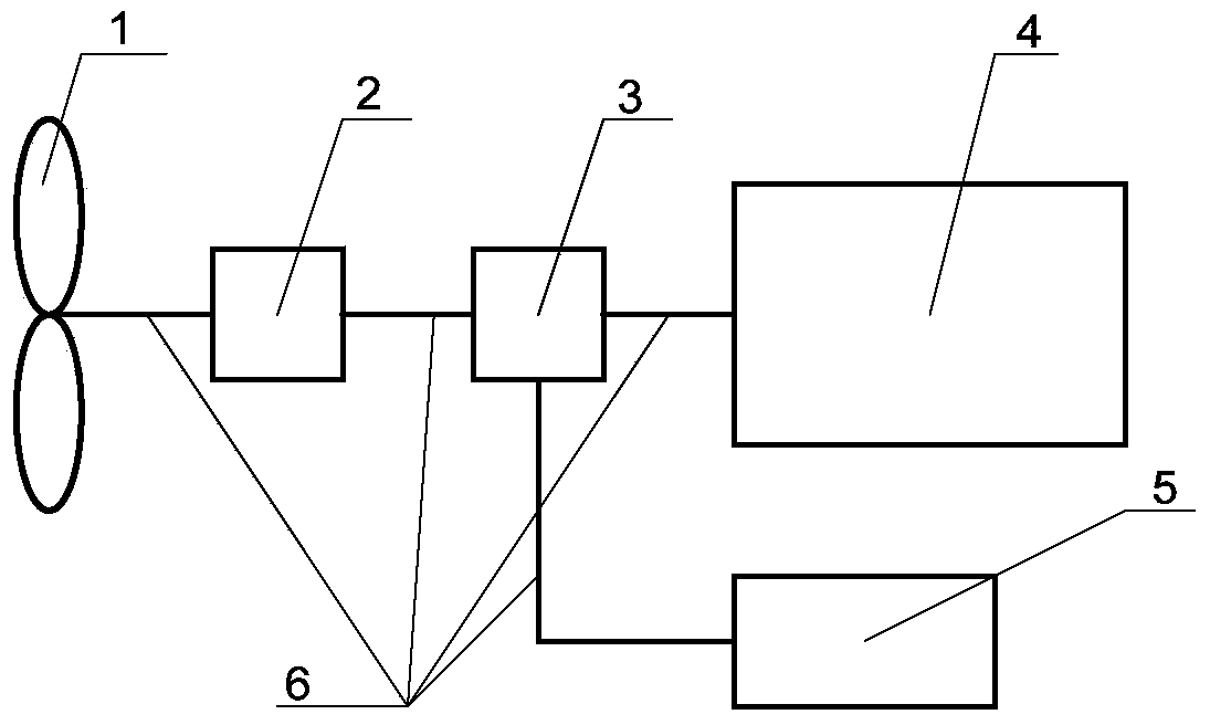
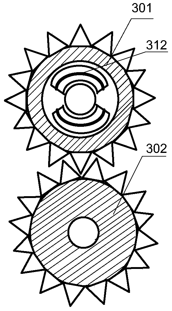
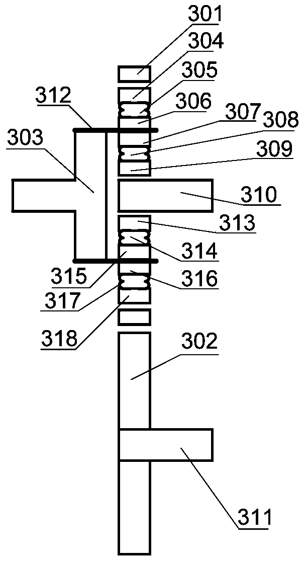
[0015] combine Figure 1~3 , the object of the present invention is to design a clutch device, which is used in wind power generating sets containing high-speed wind power generators. The machine generates electricity, so that the wind resources under high wind speed can be well utilized. According to the design standard of the wind power generator, the high wind speed referred to in the patent of the present invention is generally at 20m / s (cut-out wind speed of the low-speed wind power generator)-55m / s (the maximum wind resistance of the wind power generator).

[0016] Due to the use of high-speed permanent magnet wind generators, the structure of the wind generator set involved in the present invention is as follows: figure 1 shown. The wind turbine 1 is connected with the gearbox 2, the gearbox 2 is connected with the invented clutch 3, the clutch 3 is resp...


PUM


Abstract

The invention relates to provide a generator set applicable to low-speed wind power and high-speed wind power. The generator set comprises a wind turbine, a clutch, a low-speed permanent magnet wind generator and a high-speed permanent magnet wind generator. The clutch comprises a hollow gear, a solid gear and a hollow gear shaft, a first steel plate and a second steel plate are installed at the upper end and the lower end of the hollow gear shaft respectively, a first electromagnet, a first spring and a first armature are sequentially installed on the outer side of the first steel plate, a second electromagnet, a second spring and a second armature are sequentially installed on the inner side of the first steel plate, the inner side and the outer side of the second steel plate are of the same structure as the inner side and the outer side of the first steel plate, the inner wall of the hollow gear is located on the outer side of the first armature and the outer side of a third armature, and the solid gear is located below the hollow gear. The wind turbine is connected with the hollow gear shaft. A shaft of the low-speed permanent magnet wind generator is installed between the second armature and a fourth armature. A shaft of the high-speed permanent magnet wind generator is installed in the solid gear. The generator set can be operated normally at a low speed and at a high speed.

Description

technical field [0001] The invention relates to a power generating device, specifically a wind power generating device. Background technique [0002] Wind turbines are in a natural environment, and the wind speed changes frequently and in a large range. The wind turbines currently in operation are equipped with a cut-out wind speed, that is, the wind turbines that exceed this wind speed will be cut off from the power grid, and the control system will take normal shutdown for protection. Otherwise, it will often It will cause the generator to overspeed, overheat and cause failure. In order to ensure the long-term normal operation of the wind turbine, overspeed and overheating protection devices must be installed on the wind turbine. But at present, the existing wind turbine overspeed protection generally adopts multiple instantaneous electric short-circuit braking devices. However, in the state of strong wind, high speed of wind rotor and large rotational torque, sudden inst...

Claims


Application Information

Patent Timeline
Patent Type & Authority Applications(China)
IPC IPC(8): F03D11/02F03D9/00F03D7/04F16D27/02
CPCY02E10/722Y02E10/723Y02E10/72
Inventor 程鹏宋首男兰海张敬南黄曼磊刘宏达张强游江卢芳张镠钟
Owner HARBIN ENG UNIV
Learn More