Heat exchanger of heating pump for heating water

A technology for heat exchangers and water heating, applied in the types of heat exchangers, indirect heat exchangers, lighting and heating equipment, etc., can solve problems such as inability to meet drinking water hygiene requirements, unsatisfactory heat exchange efficiency, etc., and achieve energy saving effects Significant, easy to clean, and ensure the effect of heat exchange efficiency

Inactive Publication Date: 2014-09-03
江苏乐普四方科技有限公司
View PDF9 Cites 8 Cited by
  • Summary
  • Abstract
  • Description
  • Claims
  • Application Information

AI Technical Summary

Problems solved by technology

Although the design of this patent improves the heat exchange efficiency of the heat exchanger, the high-temperature water side channel is a circular channel with a larger diameter, but it is still closed in the heat exchange tube, which cannot solve the problem of thorough cleaning after the high-temperature water side is scaled. , after a period of use, there will be many problems such as unsatisfactory heat exchange efficiency and failure to meet the sanitary requirements of drinking water.

Method used


Image

  • Heat exchanger of heating pump for heating water
  • Heat exchanger of heating pump for heating water
  • Heat exchanger of heating pump for heating water

Examples


Embodiment 1

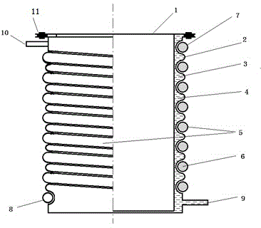
[0025] see figure 1 and figure 2 , a heat pump heat exchanger for heating water according to the present invention includes an inner tub 1 and an outer tub 2 that can be disassembled for easy cleaning, the inner tub 1 is nested inside the outer tub 2 and there is a water supply between them The flowing water flow channel 3, the water flow channel 3 in this embodiment is a spiral channel, the inward protrusions of the outer barrel 2 have the same height and are arranged at equal intervals, and the protrusions are close to the outer wall of the inner barrel 1 . In order to securely fix the inner barrel 1 and the outer barrel 2, a sealing and locking device 11 is arranged on the top of both.

[0026] The water inlet 9 is located at the bottom of the outer barrel 2, and the water outlet 10 is located at the top of the outer barrel 2 and is distributed on both sides of the outer barrel 2 with the water inlet 9; the outer peripheral wall of the outer barrel 2 is pressed to form a ...

Embodiment 2

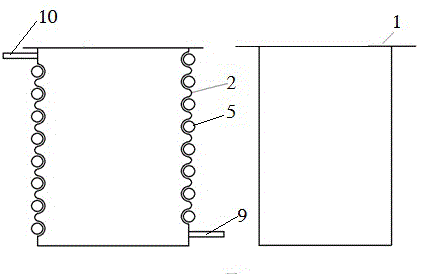
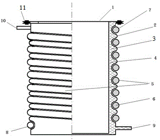
[0029] Same as embodiment 1, embodiment 2 also includes inner tub 1 and outer tub 2, the difference is that the water flow channel 3 of this embodiment is not a spiral channel, but a slit-shaped interlayer, see image 3 , that is to say, there is no contact between the inner barrel 1 and the outer barrel 2, such as Figure 6 As shown, the hollow arrow indicates the flow direction of the heating medium 6, and the solid arrow indicates the flow direction of the water flow. The heated water flows from bottom to top in the slit-like interlayer formed after the inner bucket 1 and the outer bucket 2 are nested, instead of The spiral channel of embodiment 1 flows, and in this way, since the cross-sectional area of ​​the channel is larger than that of the spiral channel of embodiment 1, and the length of the channel is smaller, it is suitable for occasions where the water flow rate is large and the temperature rise range is small.

Embodiment 3

[0031] Same as Embodiment 1, Embodiment 3 also includes an inner tub 1 and an outer tub 2, the main difference being the water flow channel 3 and the heat exchange structure 5, such as Figure 4 shown. Specifically, the outer barrel 2 has a plurality of protrusions toward the direction of the inner barrel 1, and the depths of the protrusions are different. The protrusion closest to the inner barrel 1 is in contact with the outer wall of the inner barrel 1, and the inner wall of the spiral channel It is not smooth. In fact, the water flow channel 3 can be regarded as a structure of a spiral channel combined with a narrow slit channel. The heat exchange structure 5 is not formed by a single but by multiple parallel condensing pipes, that is to say, the spiral grooves formed on the outer peripheral wall of the outer tub 2 are not as regular and consistent as in Embodiment 1. Some of the grooves are far away from the inner bucket 1, and some are close to the inner bucket 1. In th...


PUM


Abstract

The invention discloses a heat exchanger of a heating pump for heating water. The heat exchanger comprises an inner bucket and an outer bucket, wherein the inner bucket is embedded in the outer bucket; a water flow channel for water flow is formed between the inner and outer buckets; a water flow inlet is formed in the bottom of the outer bucket; a water flow outlet is formed in the top of the outer bucket; the water flow inlet and the water flow outlet are distributed at two sides of the outer bucket; a spiral groove is pressed in the outer peripheral wall of the outer bucket; and a heat exchange structure in which a heating work medium flows is arranged in the spiral groove. The heat exchanger of the heating pump for heating water has the beneficial effect that heated water and the work medium of the heating pump flow in a complete counter-current manner and the flow speeds are relatively high; the heat exchange efficiency of the heat exchanger is greatly improved; the scale formation speed is reduced; the heat exchanger adopts an open type structure, the inner and outer buckets can be detached and the washing and descaling operations can be conveniently realized, so that the heat exchange efficiency and the sanitary standard of high-temperature hot water are guaranteed, an effective solution for large scale application of a water heater of a high-temperature heating pump is provided and the energy-saving effect is remarkable.

Description

technical field [0001] The invention relates to a heat pump heat exchanger, in particular to a structure of the heat pump heat exchanger suitable for heating water. Background technique [0002] In order to quickly obtain a large amount of high-temperature hot water, especially high-temperature drinking water, heat pumps are usually used in the prior art for heat exchange. After long-term use of the heat exchanger on the high-temperature hot water side, some problems will occur, such as: low heat exchange efficiency, high-temperature hot water It is difficult to effectively increase the temperature; due to structural limitations, it is difficult to thoroughly clean and effectively descale the heat exchanger, which cannot meet the hygienic requirements of high-temperature hot water, and the fouling process is significantly accelerated under high temperature conditions, resulting in the failure of the heat pump heat exchanger in a short time There will be a significant drop in...

Claims


Application Information

Patent Timeline
Patent Type & Authority Applications(China)
IPC IPC(8): F28D7/02
Inventor 孙海龙郭永文立宁
Owner 江苏乐普四方科技有限公司
Why Eureka
Try Eureka