Tube box welding structure and manufacturing method

A welding structure and pipe box technology, applied in lighting and heating equipment, heat exchange equipment, heat exchanger shell, etc., can solve the problem of welding seam failure, splicing welding seam blanking and welding of baffle plate and oval head Difficulties and other problems, to achieve the effect of simplifying operation, improving processing capacity and heat exchange efficiency, simplifying the operation of blanking and welding

Active Publication Date: 2014-09-03
JIANGSU JIATAI EVAPORATION CRYSTALLIZATION EQUIP
View PDF6 Cites 2 Cited by
  • Summary
  • Abstract
  • Description
  • Claims
  • Application Information

AI Technical Summary

Problems solved by technology

[0003] Since the applicant introduced technical means such as forced circulation and continuous discharge into the evaporator crystallization equipment, which solved technical problems such as scaling and clogging, higher requirements were put forward for the treatment concentration and treatment efficiency of the heat exchanger. If the form of the elliptical head is still used, even if the baffle is set to increase the flow of the pipe box, it is very difficult to blank and weld the splicing weld of the baffle and the elliptical head during manufacturing, and the long-term harsh work The operation under the condition is also easy to cause the weld to fail, which has become a bottleneck in the manufacture of heat exchangers

Method used


Image

  • Tube box welding structure and manufacturing method
  • Tube box welding structure and manufacturing method
  • Tube box welding structure and manufacturing method

Examples


Embodiment

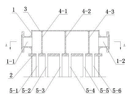
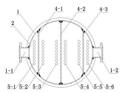
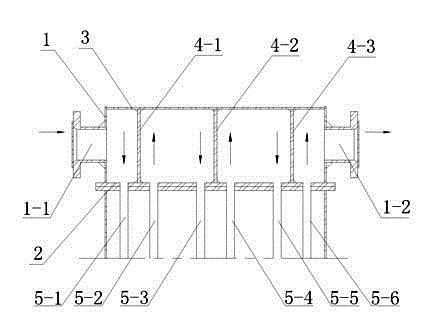
[0019] Embodiment: the pipe box welding structure of the present embodiment is as figure 1 and figure 2 As shown, it includes a vertical cylindrical barrel 1, and a feed port 1-1 for inputting materials to be processed and a discharge port 1-2 for discharging processed materials are provided on the side wall of the barrel 1, A flat-bottomed head 3 is also welded on the top of the cylinder 1, and a tube plate 2 is welded on the bottom of the cylinder 1, and the bottom of the tube plate 2 is connected to the first heating array tube 5-1, the second heating array tube 5-2, The third heating tube 5-3, the fourth heating tube 5-5, and the sixth heating tube 5-6 are in communication. In order to facilitate segmental manufacturing and splicing installation, the edge of the tube plate 2 extends to the outside of the cylinder 1 and forms a flange.

[0020] A first baffle plate 4-1, a second baffle plate 4-2 and a third baffle plate 4-3 parallel to each other are welded in the cylind...


PUM


Abstract

The invention discloses a tube box welding structure and a manufacturing method. The tube box welding structure comprises a barrel, wherein the side walls of the barrel are provided with a feed inlet and a discharge outlet respectively, a flat base end socket and a tube plate are welded to the two ends of the barrel respectively, the lower portion of the tube plate is communicated with six heating tubes, two baffle plates in the barrel divides the barrel into four chambers, the first chamber enables the feed inlet to be communicated with the first heating tube, the second chamber enables the second heating tube to be communicated with the third heating tube, the third chamber enables the fourth heating tube to be communicated with the fifth heating tube, and the sixth chamber enables the second heating tube to be communicated with the discharge outlet. The manufacturing method includes the steps of welding the barrel, the tube plate, the baffle plates and the flat base end socket in sequence. The tube box welding structure and the manufacturing method facilitate shaping of a tube box, enable welding operation to be more convenient, and better facilitate spacing distribution after baffling is completed.

Description

technical field [0001] The invention relates to a component of evaporation crystallization equipment and a manufacturing method, in particular to a pipe box welding structure and a manufacturing method. Background technique [0002] The working pressure of the heat exchanger is about 0.3Mpa, and the medium flowing inside is usually highly corrosive salty sewage. The conventional design in the chemical industry is to adopt the structure of a barrel-shaped container, and its end is made of a stamped oval head. On the one hand, the elliptical head has strong pressure resistance, and at the same time, the splicing seam between the head and the cylinder is also convenient to adopt the flat welding method on the rolling frame. [0003] Since the applicant introduced technical means such as forced circulation and continuous discharge into the evaporator crystallization equipment, which solved technical problems such as scaling and clogging, higher requirements were put forward for ...

Claims


Application Information

Patent Timeline
Patent Type & Authority Applications(China)
IPC IPC(8): F28F9/18
Inventor 树晓荣
Owner JIANGSU JIATAI EVAPORATION CRYSTALLIZATION EQUIP
Why Eureka
Try Eureka