
Digital microscope wear scar measurement device

A technology for digital microscopes and measuring devices, which is applied in the directions of measuring devices, instruments, scientific instruments, etc., can solve the problems of too large diameter of the objective lens barrel, inability to quickly locate wear spots, and great influence on accuracy, and achieves simple structure and imaging. Convenient and fast, the effect of expanding the size range

Active Publication Date: 2014-09-03
WUHAN RES INST OF MATERIALS PROTECTION
View PDF6 Cites 5 Cited by
  • Summary
  • Abstract
  • Description
  • Claims
  • Application Information

AI Technical Summary

Problems solved by technology

The existing wear scar observation devices are basically based on the four-ball testing machine wear scar optical measuring microscope. The lens barrel adopts an inclined structure with an angle of 54° with the horizontal plane, and the lens focusing adopts gear and rack cooperation, and the structure is relatively complicated. , the diameter of the objective lens barrel is too large, and the end may interfere with the observed ball; the lens and the wear scar plane are not perpendicular, and the accuracy of the wear scar diameter measurement is greatly affected by human factors; and the wear scar cannot be quickly located, and the wear scar Spot observation devices generally require a separate auxiliary light source

Method used


Image

  • Digital microscope wear scar measurement device
  • Digital microscope wear scar measurement device

Examples


Embodiment Construction

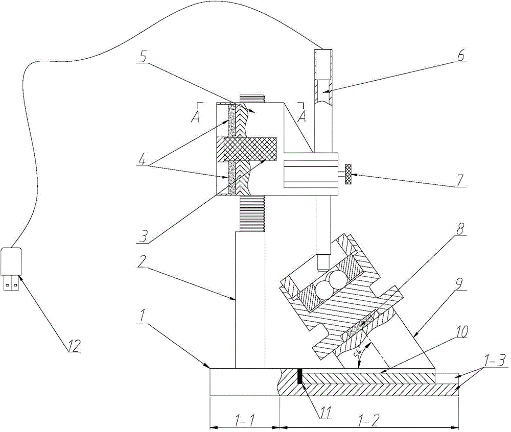
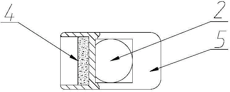
[0013] The digital microscope wear scar measuring device of the present invention comprises a base plate base 1, a support beam 5, a fine thread support rod 2, a working platform 10, a digital microscope 6, and a cylindrical oil box base 9, and the base base base consists of a base body 1-1 It is composed of the base plate 1-2, the base plate 1-2 is provided with a slide rail groove 1-3, and a limit rubber pad 11 is provided between the slide rail groove 1-3 and the inner end surface of the seat body 1-1; the cylinder oil box base The axis line of 9 and the working platform form an angle of 54° and are set on the working platform 10. Through the cooperation of the working platform and the slide rail groove 1-3, the oil box is driven to move to the limit rubber pad 11 at the inner end for positioning; the fine thread The support rod 2 is connected and fixed with the base 1-1 by screws, the support beam 5 is in surface contact with the fine thread support rod 2, and the support b...


PUM


Abstract

The invention relates to a digital microscope wear scar measurement device and belongs to the field of four-ball friction testing machine detecting equipment. The digital microscope wear scar measurement device comprises a bottom plate seat, a supporting beam, a fine thread supporting rod, a working platform, a digital microscope and a cylinder oil box base, wherein the bottom plate seat is composed of a seat body and a bottom plate, and the working platform is matched with the bottom plate in a sliding manner and provided with a sliding limiting block; the cylinder oil box base is arranged on the working platform in a manner that the axial lead of the cylinder oil box base has an included angle of 54 degrees with the working platform; the fine thread supporting rod is fixedly connected with the seat body, and the lifting of the supporting beam is adjusted relative to the fine thread supporting rod through an embedded nut of the supporting beam; two strong magnet pieces are arranged in two counter bores in one side in the supporting beam; the optical axis of the digital microscope has an included angle of 36 degrees with the axis of the cylinder oil box base, and the digital microscope is vertically connected to a connecting arm of the supporting beam. The digital microscope wear scar measurement device ensures the accurate centering and high-precision fine-tuning focal length of the working platform and provides quick and accurate observation and measurement for the wear scar detection of four-ball friction testing machines.

Description

technical field [0001] The invention discloses a digital microscope wear scar measuring device, which belongs to the field of four-ball friction tester detection equipment. Background technique [0002] The wear scar microscope is mainly used for the observation of the wear scar of the four-ball friction testing machine, observing the wear state and measuring the diameter of the wear scar. The existing wear scar observation devices are basically based on the four-ball testing machine wear scar optical measuring microscope. The lens barrel adopts an inclined structure with an angle of 54° with the horizontal plane, and the lens focusing adopts gear and rack cooperation, and the structure is relatively complicated. , the diameter of the objective lens barrel is too large, and the end may interfere with the observed ball; the lens and the wear scar plane are not perpendicular, and the accuracy of the wear scar diameter measurement is greatly affected by human factors; and the w...

Claims


Application Information

Patent Timeline
Patent Type & Authority Applications(China)
IPC IPC(8): G01N3/06
Inventor 李健白新明钱绪政段海涛徐建华
Owner WUHAN RES INST OF MATERIALS PROTECTION
Learn More