
Detection tool for lens of output jumper wire of laser device

A technology for detecting tooling and lasers, applied in the direction of optical testing flaws/defects, etc., can solve the problem of inability to directly and clearly observe the lens, etc., to achieve convenient and reliable detection, ensure cleaning work, and improve the effect of detection

Active Publication Date: 2014-09-03
WUHAN RAYCUS FIBER LASER TECHNOLOGY CO LTD
View PDF8 Cites 2 Cited by
  • Summary
  • Abstract
  • Description
  • Claims
  • Application Information

AI Technical Summary

Problems solved by technology

Under normal circumstances, the naked eye cannot directly and clearly observe the condition of the lens, so it is necessary to invent a laser output jumper lens detection device with a reasonable structure and easy operation

Method used


Image

  • Detection tool for lens of output jumper wire of laser device
  • Detection tool for lens of output jumper wire of laser device
  • Detection tool for lens of output jumper wire of laser device

Examples


Embodiment 1

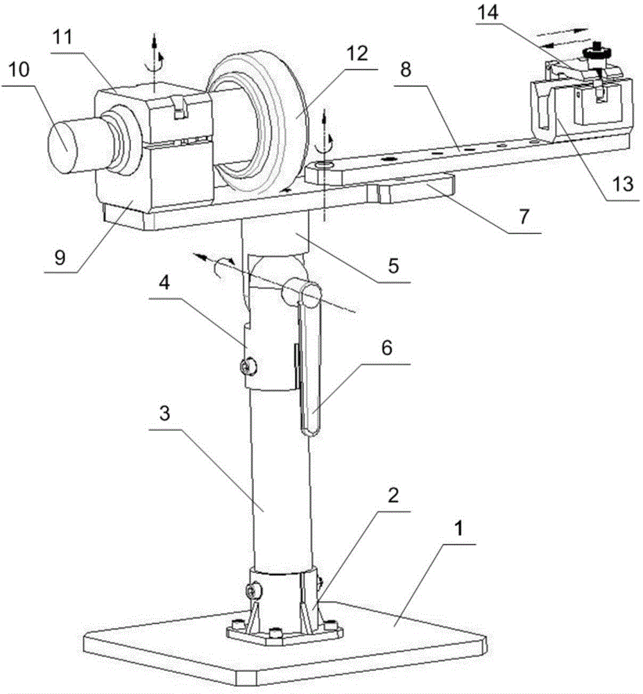
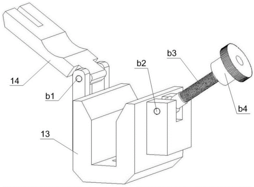
[0021] figure 1 A schematic diagram of this embodiment is shown. Referring to the figure, this embodiment consists of a rotatable bracket, a microscope group and a clamping seat, the microscope group and the clamping base are respectively installed on the rotatable bracket, and the rotatable bracket is used to support the microscope group and the clamping seat , the microscope group is used to enlarge the surface of the jumper lens for observation, and the clamping seat is used to clamp the output jumper of the laser to be tested.

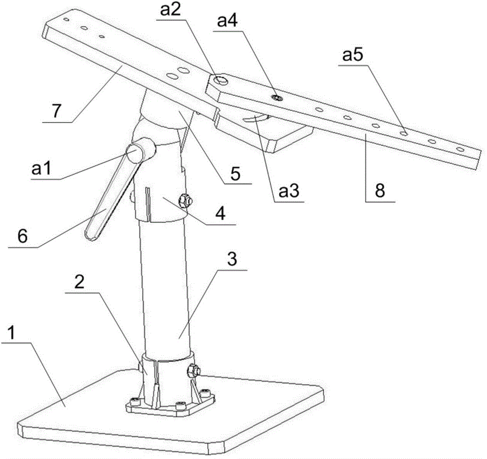
[0022] Such as figure 1 , figure 2 As shown, the rotatable bracket is composed of a bottom plate 1, a base 2, a pillar 3, a lower rotating column 4, an upper rotating column 5, a handle 6, a mounting plate 7 and a rotating plate 8; wherein the lower rotating column 4, the upper rotating column 5 It is connected with the handle 6 through the square neck screw a1; the rotation of the handle 6 can drive the rotation of the square neck screw a1, an...

Embodiment 2

[0026] The structure of the laser output jumper lens detection tool provided in this embodiment is the same as that in Embodiment 1. According to the difference between the height of the jumper to be detected and the observation environment, the angle between the upper rotating column 5 and the lower rotating column 4 can be adjusted through the handle 6, so as to observe the output jumper lens, such as Figure 4 shown.

Embodiment 3

[0028] The structure of the laser output jumper lens detection tool provided in this embodiment is the same as that in Embodiment 1. When it is necessary to detect the laser output jumper lens from different angles, the angle between the clamping seat and the microscope 10 can be adjusted by rotating the rotating plate 8 to obtain multi-angle observations, such as Figure 5 shown.


PUM


Abstract

The invention relates to a detection tool for a lens of an output jumper wire of a laser device. The detection tool is characterized by comprising a rotatably bracket, a microscope set and a clamping seat, wherein the microscope set and the clamping seat are respectively mounted on the rotatably bracket, the rotatably bracket is used for supporting the microscope set and the clamping seat, the microscope set is used for amplifying the surface of the lens of the output jumper wire so as to facilitate observation, and the clamping seat is used for clamping the to-be-detected output jumper wire of the laser device. According to the detection tool, the clamping seat is used for clamping the to-be-detected output jumper wire of the laser device, and the multiple-adjustable microscope set with an LED (light-emitting diode) lamp can be used for observing whether the lens of the jumper wire is damaged or polluted; the output jumper wire of the laser device can be simply and rapidly clamped, and lenses of output jumper wires of different laser devices can be rapidly detected by virtue of microscopes and can be conveniently cleaned.

Description

technical field [0001] The invention relates to the field of mechanical tooling, in particular to a laser output jumper lens detection tooling. Background technique [0002] The laser output jumper plays the role of transmitting the laser light. If the laser output jumper lens is damaged or unclean, the processing effect will be deteriorated, and the output jumper will be damaged in severe cases. Therefore, it is necessary to regularly inspect the laser output jumper lens. Under normal circumstances, the naked eye cannot directly and clearly observe the condition of the lens, so it is necessary to invent a laser output jumper lens detection device with a reasonable structure and easy operation. Contents of the invention [0003] The purpose of the present invention is to quickly and accurately detect or clean the laser output jumper lens, and a detection tool for the laser output jumper lens is provided. The invention can realize simple and fast clamping of the laser out...

Claims


Application Information

Patent Timeline
Patent Type & Authority Applications(China)
IPC IPC(8): G01N21/88
Inventor 张其龙夏早兵李星李杰
Owner WUHAN RAYCUS FIBER LASER TECHNOLOGY CO LTD
Learn More