Thermally driven mems micromirror and 1×n thermally driven mems micromirror array

A micromirror array, thermally driven technology, applied in microstructure technology, microstructure devices, instruments, etc., can solve the problems of low voltage drive, high mirror filling rate, reduced mirror filling rate, etc., to achieve easy rotation and control, high Mirror fill rate, the effect of reducing thermal crosstalk

Active Publication Date: 2016-04-06
无锡微文半导体科技有限公司
View PDF6 Cites 8 Cited by
  • Summary
  • Abstract
  • Description
  • Claims
  • Application Information

AI Technical Summary

Problems solved by technology

For the existing array, if the driver is arranged on the four sides of the micromirror, two-dimensional differential drive control can be realized, but the filling rate of the mirror is greatly reduced; if each direction is controlled by a single driver, the filling rate of the mirror can be improved, but not Eliminate test errors introduced by the environment
Therefore, the existing two-dimensional MEMS array cannot simultaneously realize low-voltage drive with filling rate, high mirror filling rate, and large range, and there are defects

Method used


Image

  • Thermally driven mems micromirror and 1×n thermally driven mems micromirror array
  • Thermally driven mems micromirror and 1×n thermally driven mems micromirror array
  • Thermally driven mems micromirror and 1×n thermally driven mems micromirror array

Examples


Embodiment Construction

[0024] Embodiments of the present invention will be described below in conjunction with the accompanying drawings.

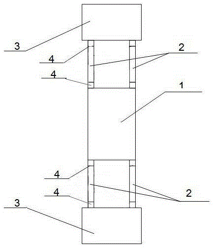
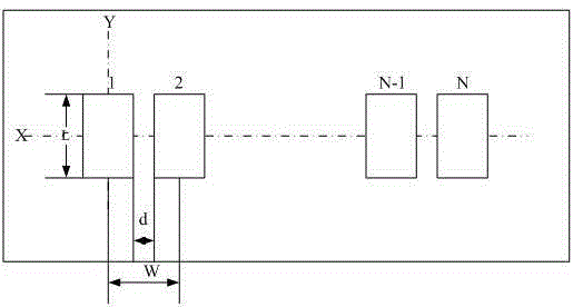
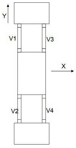
[0025] Such as figure 1 As shown, the present invention has designed a thermally driven MEMS micromirror, including a mirror surface 1, an electrothermally driven arm 2, and a micromirror frame 3. The mirror surface 1 is respectively arranged with several electrothermally driven arms 2 on the same side, and the said mirror surface 1 is arranged on the same side. Several electrothermal drive arms 2 on the same side of the mirror surface 1 are respectively connected to the micromirror frame 3, so that the two ends of the drive arm 2 are connected to the micromirror frame 3 and the mirror surface 1 respectively, so that the micromirror frame 3 is arranged in pairs on the mirror surface 1 The opposite sides of the micromirror are rotated by applying bias voltages V1, V2, V3, and V4 to each electrothermal driving arm 2 respectively. In practice, the number of electr...


PUM


Abstract

The invention disclose a thermally driven MEMS micro-mirror and a 1*N thermally driven MEMS micro-mirror array. The thermally driven MEMS micro-mirror is composed of a mirror surface, micro-mirror frames and electrical heating driving arms which are connected with the mirror surface and the micro-mirror frames. The micro-mirror frames are arranged at the opposite sides of the mirror surface in pair. The mirror surface is made to rotate by exerting bias voltage on the electrical heating driving arms. The 1*N thermally driven MEMS micro-mirror array comprises N thermally driven micro-mirror units and a substrate provided with a cavity. Each pair of micro-mirror frames are arranged on the two opposite sides on the corresponding mirror surface and are fixed to the cavity of the substrate, and the corresponding mirror surface is made to rotate by exerting bias voltage on the corresponding electrical heating driving arms. The N thermally driven micro-mirror units are arranged at an equal interval and form the 1*N micro-mirror array. According to the thermally driven MEMS micro-mirror and the 1*N thermally driven MEMS micro-mirror array, each micro-mirror is controlled independently through the corresponding electrical heating driving arms which are located on the two sides of the micro-mirror, and the length of each electrical heating driving arm can be adjusted so that design with different angle measuring ranges can be obtained; in addition, according to the design, the 1*N thermally driven MEMS micro-mirror array is driven by low voltage, is high in mirror surface filling rate and wide in measuring range, and therefore heat crosstalk can be effectively reduced.

Description

technical field [0001] The invention relates to a thermally driven MEMS micromirror and a 1×N thermally driven MEMS micromirror array formed therein, belonging to the technical field of microelectromechanical micromirrors. Background technique [0002] For a two-dimensional MEMS array, it is necessary to drive the micromirror in two directions at the same time, so the design of the driver is very important. For the existing array, if the driver is arranged on the four sides of the micromirror, two-dimensional differential drive control can be realized, but the filling rate of the mirror is greatly reduced; if each direction is controlled by a single driver, the filling rate of the mirror can be improved, but not Eliminate test errors introduced by the environment. Therefore, the existing two-dimensional MEMS array cannot realize low-voltage drive with filling rate, high mirror filling rate, and large range at the same time, which has defects. Contents of the invention ...

Claims


Application Information

Patent Timeline
Patent Type & Authority Patents(China)
IPC IPC(8): G02B26/08B81B7/00B81B7/04
Inventor 丁金玲陈巧谢会开
Owner 无锡微文半导体科技有限公司
Why Eureka
Try Eureka