Press-fit cavity power divider

A power divider and press-fit technology, which is applied to waveguide-type devices, electrical components, connecting devices, etc., can solve the problems of difficult control of processing accuracy, deterioration of overall performance indicators, and deterioration of product performance indicators, so as to enhance the environment. The effect of adaptability, shortening the processing period and shortening the production cycle

Inactive Publication Date: 2014-09-03
镇江市明基电子有限公司
View PDF5 Cites 0 Cited by
  • Summary
  • Abstract
  • Description
  • Claims
  • Application Information

AI Technical Summary

Problems solved by technology

There are four unfavorable factors in the traditional method: first, the cost of the product is high, the cavity 7 is formed by the profile, and the subsequent sequence needs to be completed by secondary processing, treatment and many other processes, and the whole process requires repeated clamping , so that the cost of the product is greatly increased, and it does not occupy any advantage in the cost of the product; the second is that the service life is low, and the structure of crimping is adopted between the cavity 7 and the cover 11, and there is an unavoidable gap between them. For long-term outdoor use, certain corrosive gases and liquids will enter the interior of the product, causing corrosion of the product and deterioration of the overall performance index. At the same time, the crimping structure of the two will increase the assembly process of the product; the third is the index performance Poor, the air and the insulator 10 are two different media, when the signal enters the interface of the insulator 10 from the air, because the insulator 10 has not done any impedance compensation processing, certain refraction will inevitably occur, greatly reducing the signal The transmission performance leads to the deterioration of the index performance of the product; the fourth is that the process is complex, because the power splitter 8 adopts a short step structure, it is difficult to control the processing accuracy, and the entire processing time is relatively long

Method used


Image

  • Press-fit cavity power divider
  • Press-fit cavity power divider
  • Press-fit cavity power divider

Examples


Embodiment

[0026] Example: Combined figure 1 — Figure 5 , the press-fit cavity power divider of this embodiment includes:

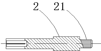
[0027] The microwave conductive rod 4 , the signal transmission cavity 3 , and the insulating medium 2 are coaxially arranged in the inner hole of the outer conductor 3 .

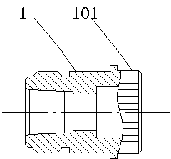
[0028] The signal transmission cavity 3 has an outer square and an inner circle, which is an integral structure through die-casting, and coincides with the central axis of the microwave conductive rod 4, and is press-fitted and connected through the press-fitted rule 101 of the outer conductor 1;

[0029] One end of the microwave conductive rod 4 is provided with an input press-fit hole 41 of a coaxial structure, and the other end is provided with an output press-fit hole 42 of a vertical structure. shape, the microwave conductive rod 4 is press-fitted and connected through the press-fitted rule 21 of the inner conductor 2;

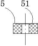
[0030] One side of the insulating medium 5 is provided with an imp...


PUM


Abstract

The invention discloses a press-fit cavity power divider which comprises a microwave conducting rod and a signal transmission cavity which are successively coaxially arranged, internal conductors directly connected with the microwave conducting rod, external conductors directly connected with the signal transmission cavity and insulating mediums which are coaxially arranged between the internal conductors and the external conductors. The microwave conducting rod is successively in a trapezoid step shape from an input press-fit hole to an output press-fit hole. The signal transmission cavity and the microwave conducting rod are coaxially arranged. The insulating mediums are positioned between the internal conductors and the external conductors. Thus, relative fixation between the internal conductors and the external conductors is realized, and central axis of the insulating mediums overlap central axis of the internal conductors and the external conductors. The invention relates to a press-fit cavity power divider which has advantages of simple structure, reliable mechanical property, excellent electrical property, high transmission power, high production efficiency and low cost and is suitable for mass production.

Description

Technical field: [0001] The invention relates to a press-fit cavity power divider. Background technique: [0002] At present, the traditional cavity power splitter generally adopts a short ladder structure, the connector shell 6 and the cavity 7 are threaded, and the pin 9 and the power splitter 8 are threaded. Such as Figure 6 It is a traditional cavity power divider structure. Before the production of the product, the cover 11 is crimped into the groove on the top of the cavity 7 using a press; the specific product assembly is to crimp the insulator 10 into the shell 6, Pre-install the pin 9 into the corresponding threaded mounting hole of the power splitter 8, fasten the pin 9 and the power splitter 8 with a wrench, install the power splitter 8 into the cavity 7, and finally install the shell 6 is pre-installed on the cavity 7, and the shell 6 and the cavity 7 are fastened with a dead wrench, so that the assembly of the traditional cavity power divider can be completed....

Claims


Application Information

Patent Timeline
Patent Type & Authority Applications(China)
IPC IPC(8): H01P5/12
Inventor 王征亮沈学光
Owner 镇江市明基电子有限公司
Why Eureka
Try Eureka