Electric-energy optimal control method for intelligent micro-grid with energy storage device

A technology for power optimization and energy storage equipment, applied in electrical components, circuit devices, AC network circuits, etc., can solve the problems of long time span, insignificant control effect, and difficulty in establishing a mechanism model for battery power, so as to reduce peak and valley loads. difference, increase flexibility and compatibility, and reduce electricity costs

Active Publication Date: 2014-09-03
INST OF AUTOMATION CHINESE ACAD OF SCI
View PDF2 Cites 24 Cited by
  • Summary
  • Abstract
  • Description
  • Claims
  • Application Information

AI Technical Summary

Problems solved by technology

[0004] However, during the actual operation of the energy storage battery, the change of load at the residential user end involves human subjective factors, which is difficult to predict accurately. At the same time, the long time span, the short-term control effect is not obvious, and the nonlinearity is serious, making it difficult to establish an accurate mechanism for battery power. model, which brings great difficulties to the optimal control of battery power in smart grids

Method used


Image

  • Electric-energy optimal control method for intelligent micro-grid with energy storage device
  • Electric-energy optimal control method for intelligent micro-grid with energy storage device
  • Electric-energy optimal control method for intelligent micro-grid with energy storage device

Examples


Embodiment Construction

[0019] In order to more clearly illustrate the purpose, technical solutions and advantages of the present invention, the present invention will be further described in detail below in conjunction with specific embodiments and with reference to the accompanying drawings.

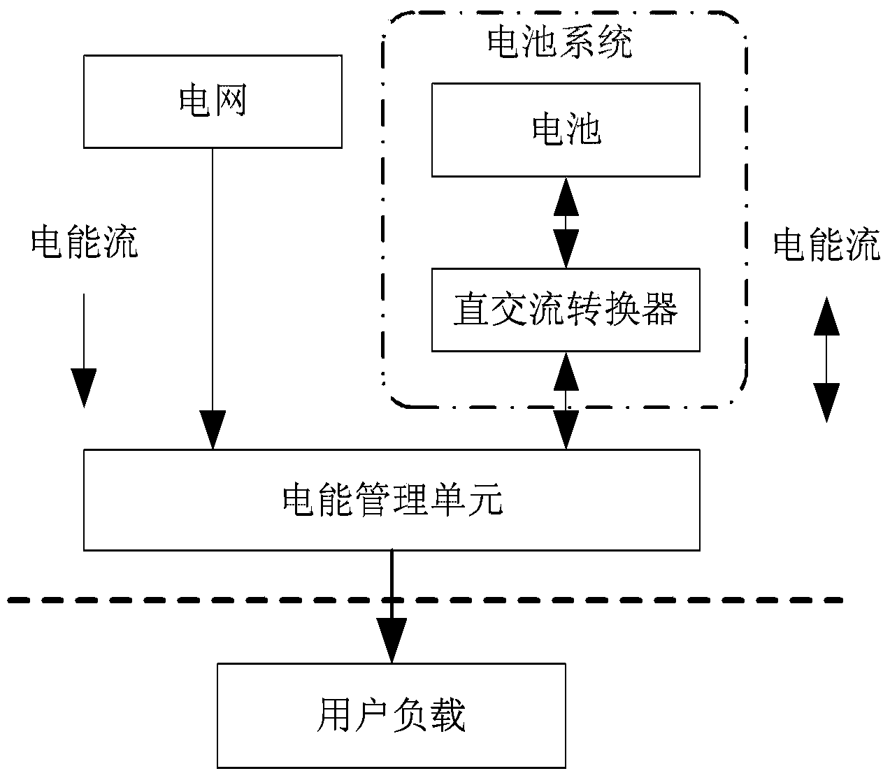
[0020] figure 1 It is a structural schematic diagram of the intelligent house system in the present invention. Such as figure 1 As shown, the smart residential system is composed of power grid, user load, battery system (including battery and DC-AC converter) and power management unit (controller). The battery is connected to the power management unit through a DC-to-AC converter.

[0021] In this smart residential system, the battery adopts different control strategies to meet the needs of user load and real-time electricity price. Batteries in smart home systems have three modes of operation. 1. Charging mode: When the user load is low and the electricity price is low, the grid directly meets the user l...


PUM


Abstract

The invention discloses an electric-energy optimal control method for an intelligent micro-grid with an energy storage device. The method comprises the steps that relevant parameters are initialized; global iteration is started, evaluation network weights and executive network weights are initialized; local iteration is started, an evaluation network and an executive network are trained by utilizing a self-adapting dynamic planning method, and neural network weights are corrected, wherein the evaluation network is used for approximating to an optimal performance index function, and the performance of the current battery control strategy is evaluated by utilizing the evaluation network weights; the executive network is used for approximating to an optimal control strategy and minimizing total cost in the primary global iteration; whether the current local iteration is completed or not is judged, if not, the local iteration is repeated, and if yes, an iteration performance index function and an iteration control law are updated to obtain the optimal solution; whether the current global iteration meets convergence precision or not is judged, if not, the global iteration is repeated, if yes, an optimal battery control strategy is obtained according to the optimal performance index function, and power utilization cost is calculated.

Description

technical field [0001] The invention belongs to the technical field of smart grid electric energy optimization, and in particular relates to an electric energy optimization control method of an intelligent micro-grid with energy storage equipment. Background technique [0002] Batteries, also known as rechargeable batteries, are commonly used energy storage devices for smart microgrid users' residential terminals. They store chemical energy and convert chemical energy directly into electrical energy when necessary. The storage battery is carefully designed to be rechargeable, and recharging is realized through a reversible chemical reaction. Taking into account various aspects such as comprehensive cost, the battery for energy storage is mainly lead-acid battery. The working process is: when charging, the external electric energy is used to regenerate the internal active material, the electric energy is stored as chemical energy, and the chemical energy is converted into ele...

Claims


Application Information

Patent Timeline
Patent Type & Authority Applications(China)
IPC IPC(8): H02J3/00H02J3/28G06Q10/04G06Q50/06
CPCY04S10/545Y02E40/76Y02E40/70Y04S10/50
Inventor 刘德荣魏庆来石光
Owner INST OF AUTOMATION CHINESE ACAD OF SCI
Why Eureka
Try Eureka