Digital control method of three-level pfc circuit

A digital control, three-level technology, applied in the direction of high-efficiency power electronic conversion, electrical components, output power conversion devices, etc., can solve the problems of difficulty, increase the complexity of the device, and complex algorithms, and achieve less sampling data and more computing power. The effect of low ability requirements and simple algorithm

Inactive Publication Date: 2016-08-24
GUANGDONG UNIV OF TECH
View PDF7 Cites 0 Cited by
  • Summary
  • Abstract
  • Description
  • Claims
  • Application Information

AI Technical Summary

Problems solved by technology

[0003] At present, there are many methods for the control of three-level PFC circuits. Chinese patents 200910145279.1 and 200710080000.7 both provide a space vector control method, and 200910128568.0 provides a method for optimizing switching operations to ensure that the phase of the current is consistent with the voltage; domestic journals Some people also provide one-cycle (One-Cycle) control methods in the literature; these control methods have their own characteristics. Vector control is a control method based on digital chips, which can be flexibly applied in practice and is suitable for high-power applications. However, its algorithm is relatively complicated, and it needs to sample the input voltage, input current, output voltage and current of the three phases, which increases the complexity of the device; the method of single-cycle control is relatively simple, no need to sample the input voltage, only need to Current and output voltage are sampled, but because real-time input current is required to participate in the comparison to obtain the control amount, it is difficult to use digital chips to achieve single-cycle control

Method used


Image

  • Digital control method of three-level pfc circuit
  • Digital control method of three-level pfc circuit
  • Digital control method of three-level pfc circuit

Examples


Embodiment Construction

[0052] The present invention will be further described in conjunction with the following examples.

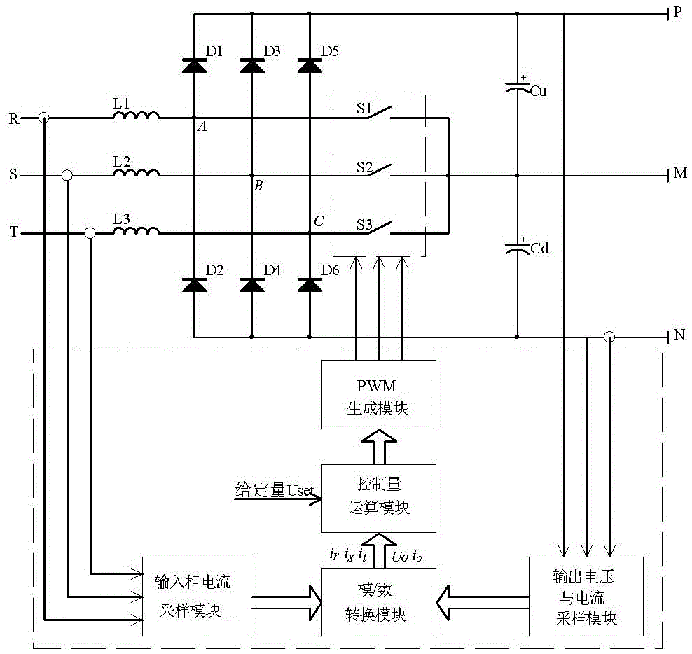
[0053] Such as Figure 1 to Figure 3 As shown, the digital control system of the three-level PFC circuit includes

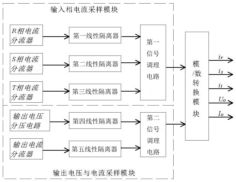
[0054] The input phase current sampling module is used for sampling the input phase current signal;

[0055] Output voltage and current sampling module, used for sampling output voltage signal and output current signal;

[0056] The analog / digital conversion module is used to convert the input phase current signal, the output voltage signal and the output current signal, so as to obtain the R-phase input current i r , S-phase input current i s , T-phase input current i t , output voltage U O , output current I O ;

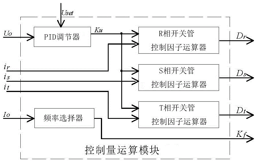
[0057] The control quantity operation module is used for inputting the current i of the R phase r , S-phase input current i s , T-phase input current i t , output voltage U O , output current I O Carry out calculation to obtain the control ...


PUM


Abstract

The invention relates to the technical field of power electronic circuit digital control, in particular to a digital control system and method for a three-level PFC circuit. The digital control system comprises an input phase current sampling module, an output voltage and current sampling module, an analog-digital conversion module, a control quantity operation module and a PWM generation module. After being converted by the analog-digital conversion module, an output voltage signal generates voltage control factors through the control quantity operation module; after being converted by the analog-digital conversion module, an output current signal generates frequency selection factors through the control quantity operation module; after being converted by the analog-digital conversion module, the input phase current generates switch tube control factors through the control quantity operation module; the voltage control factors, the frequency selection factors and the switch tube control factors form PWM control quantity through the PWM generation module. According to the digital control system and method for the three-level PFC circuit, output positive and negative bus voltage balance is achieved, and high power factors can be obtained when loads in different levels exist.

Description

technical field [0001] The invention relates to the technical field of digital control of power electronic circuits, in particular to a digital control method of a three-level PFC circuit. Background technique [0002] The topology of the three-level power factor correction (PFC) circuit is shown in Figure (1), where R, S, and T are three-phase AC voltage inputs, and the inputs of each phase are respectively connected to inductors L1, L2, and L3, and the other ends of the inductors are respectively connected to The midpoints A, B, and C of the bridge circuit composed of diodes D1, D2, D3, D4, D5, and D6, and the N poles of diodes D1, D3, and D5 are commonly connected to the output capacitor C u The positive pole is the positive pole output P of the circuit, and the P poles of diodes D2, D4, and D6 are commonly connected to the output capacitor C d The negative pole is the negative pole output N of the circuit, and S1, S2, and S3 are three corresponding switch tubes, which a...

Claims


Application Information

Patent Timeline
Patent Type & Authority Patents(China)
IPC IPC(8): H02M1/42
CPCY02B70/10
Inventor 周映虹黄熙陈小琴
Owner GUANGDONG UNIV OF TECH
Why Eureka
Try Eureka