Reinforced high-pressure GIS (gas insulated switchgear) shell

An enhanced, high-pressure technology, applied in the field of GIS shells, can solve the problems of large machining allowance, welding cracks, incomplete penetration, and uneven thickness, so as to improve welding quality, reduce welding stress, and reduce weld seam differences. Effect

Inactive Publication Date: 2014-09-10
JIANGSU HAIDA ELECTRIC
View PDF0 Cites 7 Cited by
  • Summary
  • Abstract
  • Description
  • Claims
  • Application Information

AI Technical Summary

Problems solved by technology

[0002] The high-voltage GIS (Gas Insulated Switchgear gas-insulated metal-enclosed switchgear) shell is a key component of high-voltage combined electrical appliances, including flanges and cylinders at both ends; one side of the flange has an inner hole that matches the outer diameter of the cylinder. Seam; the two ends of the cylinder have inner grooves in the inner hole; the cylinder and the inner seam are welded and fixed between the flanges at both ends after assembly; the previous structure is: the upper end surface of the inner seam is only deburred, and the Deep impurities cannot be cleaned after the spigot is assembled, and the outer fillet weld is not easy to merge with the inner weld during welding, resulting in low quality welds of the shell, prone to welding defects such as pores, inclusions, welding cracks, and incomplete penetration, which affect the shell The use effect of the body greatly reduces its lifespan
On the other hand, in the conventional butt joint method between the cylinder body and the flange, the outer fillet weld is larger than the inner weld, and the lateral shrinkage of the outer fillet weld is greater than that of the inner and inner welds, resulting in the hook deformation of the flange, and the inside and outside of the flange. The deviation between the end face and the cylinder axis is large, and secondary processing is required, the processing allowance is too large, and the thickness of the flange after processing is uneven

Method used


Image

  • Reinforced high-pressure GIS (gas insulated switchgear) shell
  • Reinforced high-pressure GIS (gas insulated switchgear) shell

Examples


Embodiment Construction

[0013] The present invention will be further described below according to the accompanying drawings and in conjunction with the embodiments.

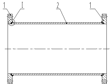
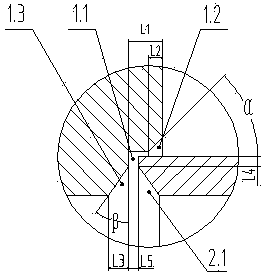
[0014] The reinforced high-pressure GIS shell shown in the accompanying drawings includes a cylinder body 2 and flanges 1 at both ends; the inner hole of the flange 1 is provided with an inner stop 1.1 on one end surface; the inner holes at both ends of the cylinder body 2 are provided with Inner bevel 2.1; Flange 1 inner stop 1.1 is set on the cylinder body 2 and fixedly connected by welding; inner stop 1.1 depth L1 is 0.9 to 1 times the wall thickness of the cylinder body 2, in this embodiment, the inner stop The depth L1 of the mouth 1.1 is 1 time of the wall thickness of the cylinder 2; the upper end surface of the internal stop 1.1 is chamfered, the chamfer angle α is 45°~55°, and the depth L2 is 0.4~0.5 times of the wall thickness of the cylinder 2, In this embodiment, the chamfering angle α is 45°, the depth L2 is 0.5 times the w...


PUM


Abstract

The invention discloses a reinforced high-pressure GIS (gas insulated switchgear) shell. The reinforced high-pressure GIS shell comprises a barrel and flanges at two ends of the barrel. An inner seam allowance is arranged on the end face of one side of an inner hole of each flange; an inner groove is arranged in the orifice of an inner hole at each of two ends of the barrel; the inner seam allowances sleeve the barrel at intervals and are fixedly connected with the same by welding; the depth L1 of each female end is 0.9-1 times of the wall thickness of the barrel; the upper end face of each inner seam allowance is provided with a chamfer 45 degrees to 55 degrees in angle alpha, and the depth L2 of the chamfer is 0.4-0.5 times of the wall thickness of the barrel; the lower end face of each inner seam allowance is provided with another chamfer 35 degrees to 40 degrees in angle beta, and the depth L3 of the chamfer is 0.5-0.7 times of the wall thickness of the barrel; the length L4 of the truncated edge of each inner groove is 0.2 to times of the wall thickness of the barrel; further, gaps are reserved between the end face of the barrel and the lower end faces of the inner seam allowances. The reinforced high-pressure GIS shell is convenient to clean before welding, small in welding stress and welding deformation and small in allowance of secondary machining of the flanges.

Description

technical field [0001] The invention relates to the field of high-voltage substations, in particular to a GIS shell. Background technique [0002] The high-voltage GIS (Gas Insulated Switchgear gas-insulated metal-enclosed switchgear) shell is a key component of high-voltage combined electrical appliances, including flanges and cylinders at both ends; one side of the flange has an inner hole that matches the outer diameter of the cylinder. Seam; the two ends of the cylinder have inner grooves in the inner hole; the cylinder and the inner seam are welded and fixed between the flanges at both ends after assembly; the previous structure is: the upper end surface of the inner seam is only deburred, and the Deep impurities cannot be cleaned after the spigot is assembled, and the outer fillet weld is not easy to merge with the inner weld during welding, resulting in low quality welds of the shell, prone to welding defects such as pores, inclusions, welding cracks, and incomplete p...

Claims


Application Information

Patent Timeline
Patent Type & Authority Applications(China)
IPC IPC(8): B23K33/00
CPCB23K33/00
Inventor 田江
Owner JIANGSU HAIDA ELECTRIC
Why Eureka
Try Eureka