
Electric injection device for injection molding machine

An injection device and injection molding machine technology, applied in the field of injection devices, can solve the problems of reducing the injection performance of the injection molding machine, increasing the injection start-up time, etc., and achieve the effects of shortening the injection start-up time, improving the injection performance, and realizing mutual independence.

Inactive Publication Date: 2014-09-10
宁波海雄塑料机械有限公司
View PDF6 Cites 9 Cited by
  • Summary
  • Abstract
  • Description
  • Claims
  • Application Information

AI Technical Summary

Problems solved by technology

However, during the injection and glue pumping of this invention, the components such as the storage servo motor and the headstock move back and forth following the roller screw assembly. During the injection and glue pumping process, due to the excessive weight of the moving parts, the injection startup time is increased. , reducing the injection performance of the injection molding machine

Method used

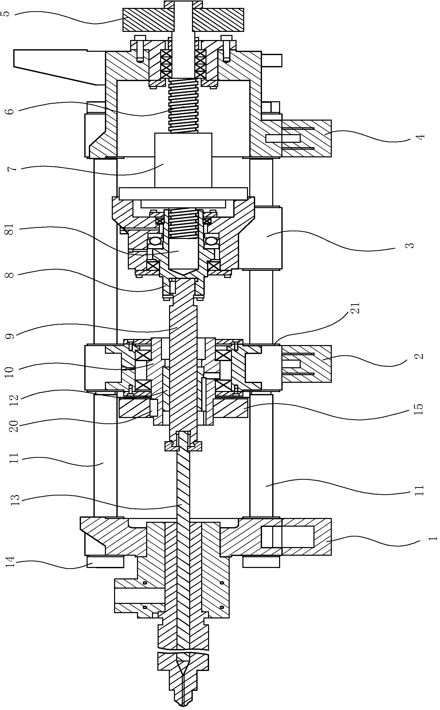
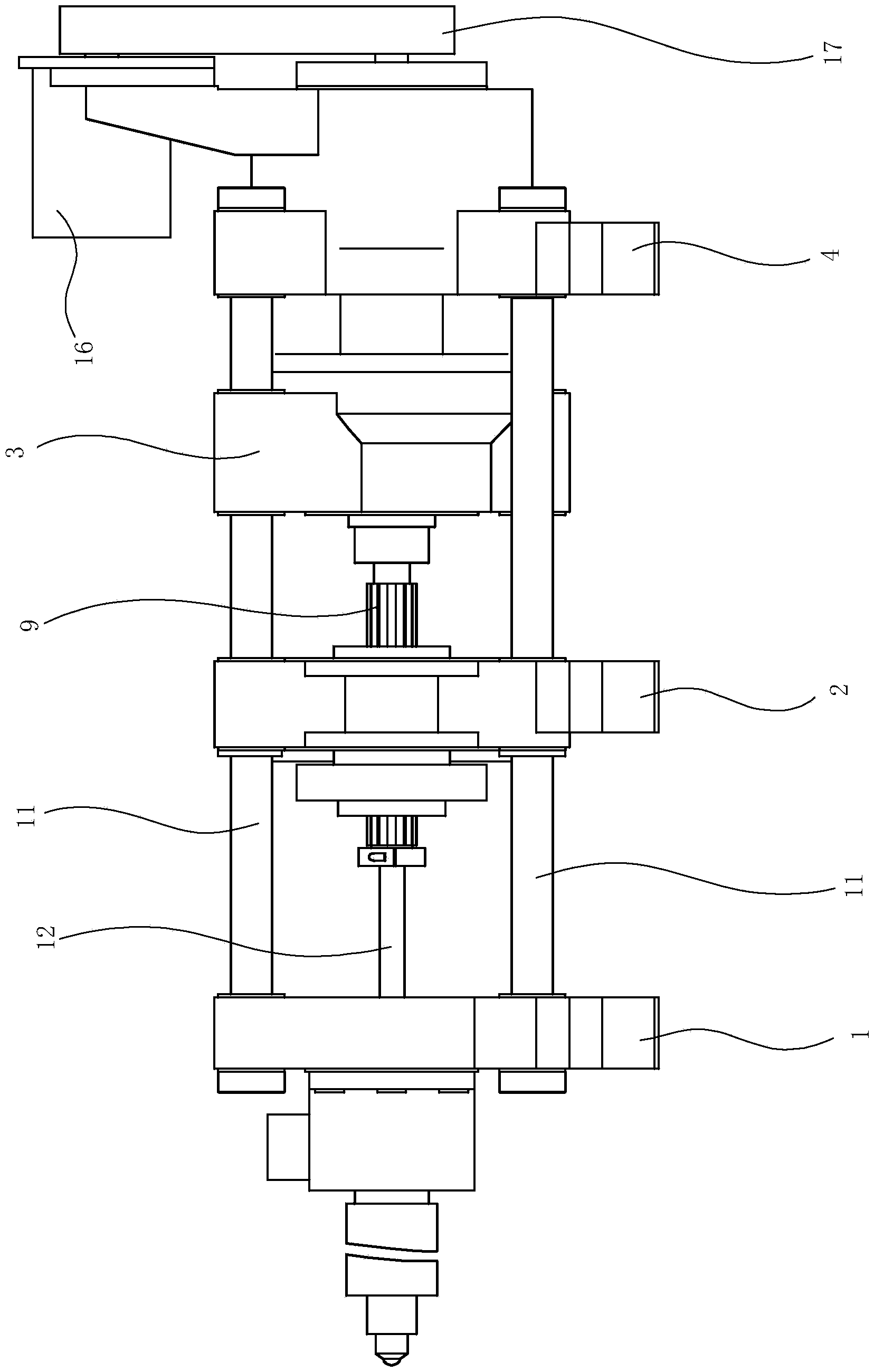
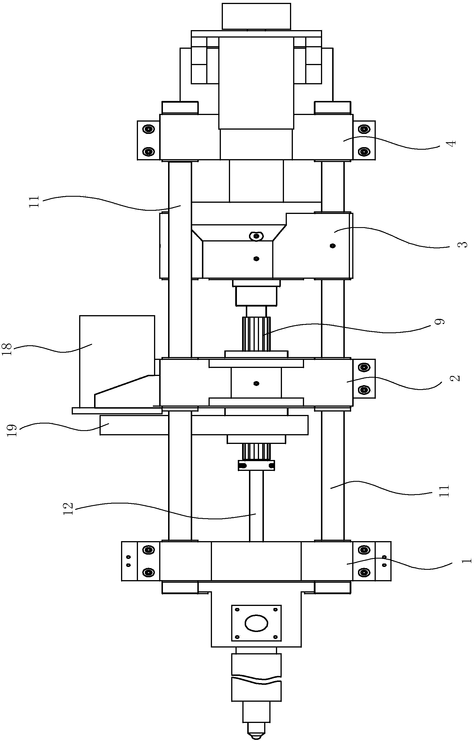

Image

  • Electric injection device for injection molding machine
  • Electric injection device for injection molding machine
  • Electric injection device for injection molding machine

Examples


Embodiment Construction

[0015] The present invention will be further described in detail below in conjunction with the accompanying drawings and embodiments.

[0016] Such as Figures 1 to 3 As shown, the electric injection device of the injection molding machine in this implementation includes an injection front plate 1, an injection tail plate 4, an injection rod 11, a rod nut 14, a screw 13, a roller screw 6, a nut 7, an injection motor 16, and an injection synchronous Belt 17, injection driven wheel 5, injection moving plate 3, injection middle plate 2, pressure transmission shaft 8, spline shaft 9, spline sleeve 12, transmission shaft 10, melt glue motor 18, melt glue synchronous belt 19, melt glue slave The ball screw pair is formed between the moving wheel 15, the flat key 20, the nut 7 and the roller screw 6, and the spline pair is formed between the spline sleeve 12 and the spline shaft 9.

[0017] Among them, four injection rods 11 are pierced between the injection front plate 1 and the in...


PUM


Abstract

The invention discloses an electric injection device for an injection molding machine. The electric injection device comprises a screw rod which is arranged in an injection front plate in a penetrating manner and a pin roller screw rod pair, wherein the pin roller screw rod pair comprises a nut and a pin roller screw rod arranged in an injection tail plate in the penetrating manner. The electric injection device is characterized in that the tail of an injection movable plate is fixedly connected with the nut; the injection movable plate is internally and rotatably provided with a pressure transmission shaft; the front end of the pressure transmission shaft is connected with a spline shaft; the other end of the spline shaft is connected with the screw rod; an injection middle plate is internally and rotatably provided with a transmission shaft; the transmission shaft is internally sleeved with a spline sleeve; a spline pair is composed of the spline sleeve and the spline shaft. With the adoption of the spline pair, the weight of a movement part in the injection process is lightened and the injection performance of the injection molding machine is improved.

Description

technical field [0001] The invention relates to an injection device, in particular to an electric injection device for an injection molding machine. Background technique [0002] Injection molding machine is the main molding equipment for making thermoplastics or thermosetting plastics into various shapes of plastic products using plastic molding molds. Among them, the injection system of the injection molding machine is one of the most important components of the injection molding machine. In a cycle of the injection molding machine, the injection system can heat and plasticize a certain amount of plastic within a specified time, and then under a certain pressure and At high speed, the molten plastic is injected into the mold cavity by the screw. During the injection process of the injection molding machine, the power transmission device in the injection system needs to complete the injection, glue pumping and melting actions. [0003] For this reason, the Chinese inventi...

Claims


Application Information

Patent Timeline
Patent Type & Authority Applications(China)
IPC IPC(8): B29C45/03B29C45/46
CPCB29C45/47
Inventor 张卫东郑强袁能杰
Owner 宁波海雄塑料机械有限公司
Learn More