
Track component for maglev train

A technology for maglev trains and tracks, applied in the field of track components for maglev trains, can solve problems such as the inability to meet high-efficiency operating speeds, the inability to reduce the air gap of traction motors, and the discontinuity of stator coils, etc., and achieve simple structure, reduced quantity, and smooth routes The effect of increased adaptive capacity

Inactive Publication Date: 2014-09-10
NAT UNIV OF DEFENSE TECH
View PDF12 Cites 37 Cited by
  • Summary
  • Abstract
  • Description
  • Claims
  • Application Information

AI Technical Summary

Problems solved by technology

[0005] 1. This traction method cannot meet the high-efficiency operating speed (the maximum operating speed is only about 100 kilometers per hour)
[0006] 2. The motor coils using this traction method must be installed on the vehicle, and must be equipped with vehicle-mounted traction equipment such as high-voltage circuit systems, filter reactors, traction inverters, linear motors, and braking resistors. The traction equipment is complex
[0007] 3. In practical applications, the safe operation of the train requires a suspension gap of about 8mm between the vehicle and the track. Since the motor must not touch the track when the vehicle lands, and there are installation errors between the track and the motor, the air gap of the traction motor is generally guaranteed. At about 15mm, the air gap of the traction motor is large, and the air gap of the traction motor cannot be reduced due to the above reasons. Reduce the efficiency of the motor, resulting in low traction efficiency and low energy utilization
After electrification, the moving traveling wave magnetic field can be generated in the long stator coil, which acts on the vehicle-mounted suspension magnet to generate synchronous electromagnetic traction, and the traction train runs. It can be seen that the system structure is complex, the turning radius is large, the line selection is not flexible, and the control system complex

Method used


Image

  • Track component for maglev train
  • Track component for maglev train
  • Track component for maglev train

Examples


Embodiment Construction

[0029] The present invention will be further described in detail below in conjunction with the accompanying drawings and specific embodiments.

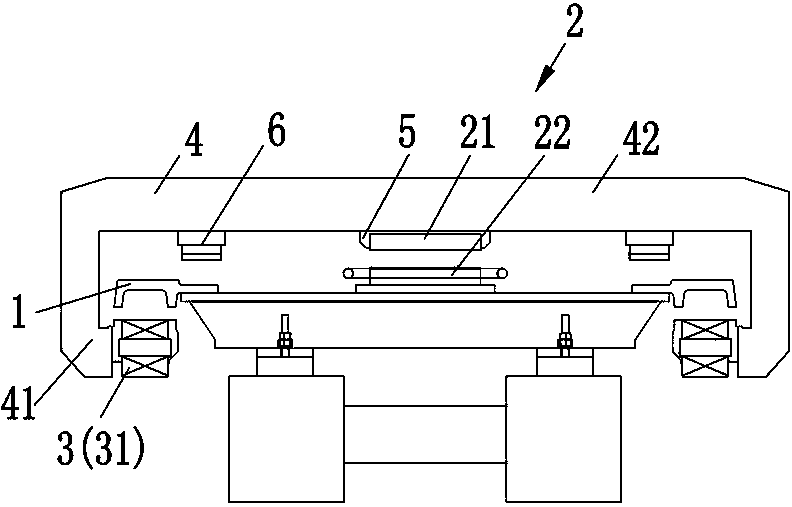
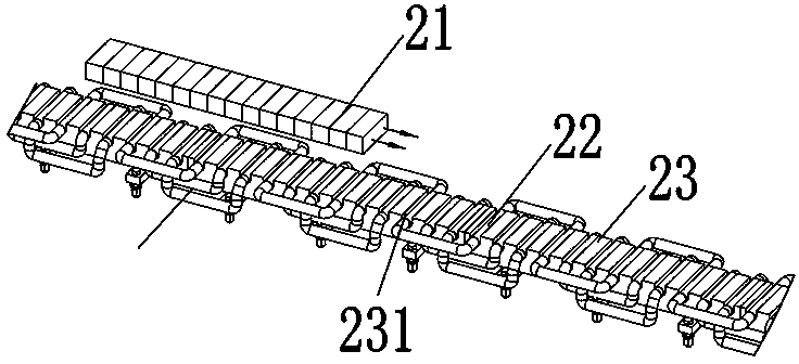
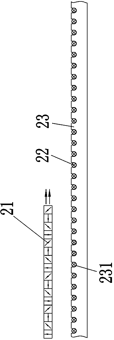
[0030] Such as Figure 1 to Figure 3 As shown, the track assembly of the maglev train of the present embodiment comprises track 1, bogie 4, traction module 2 and suspension guide module 3, track 1 adopts F rail, suspension guide module 3 is located at the both sides of track 1, and bogie 4 is set on the car body of the maglev train, and the traction module 2 is set at the middle position of the track 1. The traction module 2 adopts a synchronous linear motor mode, and includes array structure permanent magnets 21 and long stator coils 22 arranged oppositely, and the array structure permanent magnets 21 As the traction force receiving part of the vehicle, it is installed on the inner side of the bogie 4 through the permanent magnet fixing frame 5, and the long stator coil 22 is installed on the track 1, and the long stator coil 22 is p...


PUM


Abstract

The invention discloses a track component for a maglev train. The track component comprises a track, a bogie arranged on a maglev train body, a traction module, and levitation guide modules arranged on two sides of the track. The traction module is disposed in the middle of the track and comprises array structured permanent magnets in corresponding arrangement and a long stator coil; power supply is controlled for the long stator coil via the ground; the array structured permanent magnets are mounted on the bogie; the long stator coil is mounted on the track; the long stator coil and the array structured permanent magnets interact to produce tractive force for the maglev train. The track component has the advantages that utilization rate of energy resources is increased, energy consumption is lowered and vehicular equipment is simplified.

Description

technical field [0001] The invention relates to the field of maglev trains, in particular to a track assembly suitable for a maglev train. Background technique [0002] The maglev train is a rail vehicle that uses electromagnetic force to realize the non-contact support and guidance of the train, and realizes non-contact traction and braking through linear motors. At present, relatively mature maglev trains include low-speed maglev trains and high-speed maglev trains, which have three basic functions of suspension, guidance and traction. Suspension refers to the non-contact between the maglev train and the track, and guidance is to realize the steering and anti-rolling of the maglev train. Traction is to realize the forward moving function of the maglev train. [0003] The traction of low-speed maglev trains adopts asynchronous induction mode, which has the advantages of simple structure, small turning radius and low noise. Its suspension (guiding) and traction components ...

Claims


Application Information

Patent Timeline
IPC IPC(8): B61B13/08B60L13/04
Inventor 李云钢程虎董钟刘恒坤龙娟
Owner NAT UNIV OF DEFENSE TECH
Learn More