Gas Charging Method And Gas Charging Apparatus For Bag Equipped With Gas Compartment Portion

A gas and bag technology, applied in gas/liquid distribution and storage, packaging objects under special gas conditions, container filling methods, etc., can solve problems such as separation, difficult productivity, and improvement

Active Publication Date: 2014-09-10
TOYO JIDOKI CO LTD
View PDF10 Cites 8 Cited by
  • Summary
  • Abstract
  • Description
  • Claims
  • Application Information

AI Technical Summary

Problems solved by technology

In addition, since the gas filling method of Patent Document 2 cannot separate the process of filling the air bag with gas and the process of sealing gas, when applying it to, for example, an intermittent rotation type rotary packaging device, it is necessary to stop at the same stop position. Compared with the gas filling method of Patent Document 1, it is difficult to improve productivity

Method used


Image

  • Gas Charging Method And Gas Charging Apparatus For Bag Equipped With Gas Compartment Portion
  • Gas Charging Method And Gas Charging Apparatus For Bag Equipped With Gas Compartment Portion
  • Gas Charging Method And Gas Charging Apparatus For Bag Equipped With Gas Compartment Portion

Examples


Embodiment Construction

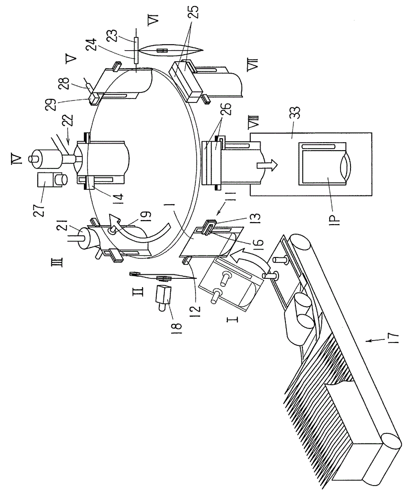
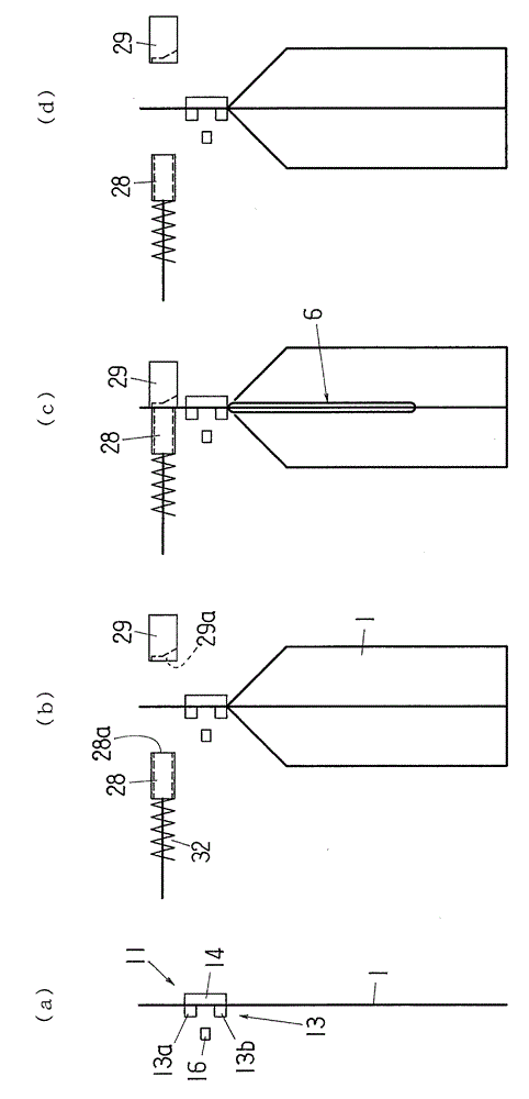
[0036] Below, refer to Figure 1 to Figure 9 , the gas filling method and apparatus according to the present invention will be described in detail.

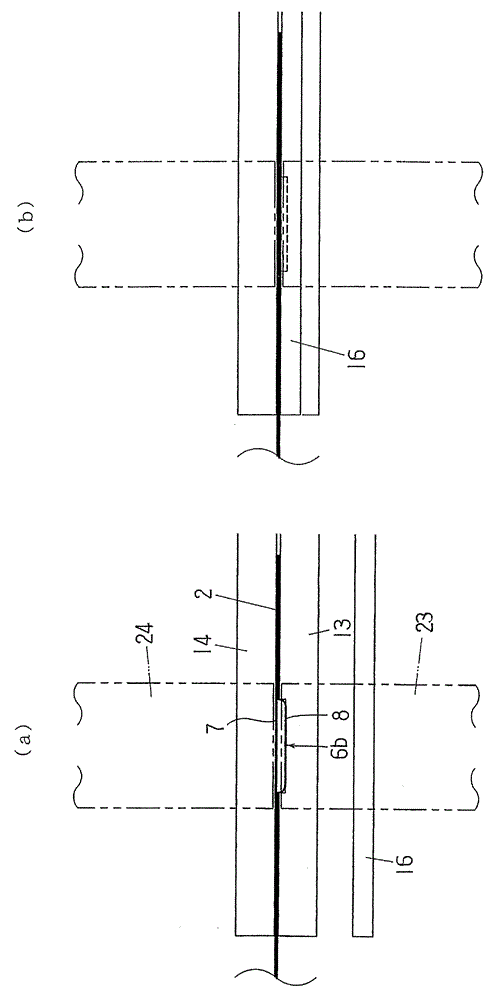
[0037] exist Figure 5 Shown in is bag 1 with air bag attached. The bag 1 is a self-supporting bag with a gusseted bottom, and is composed of films on both the front and back sides and a folded bottom film. In the upper region X of the bag 1 , at the two side edges, the films on both the front and back sides of the bag 1 are bonded to each other, forming seals 2 , 3 . At the upper edge, the films on both sides of the front and the back are not bonded, forming an open bag mouth 4 . In the lower region Y of the bag 1, at the two side edges, the films on both the front and back sides are bonded with the bottom film sandwiched between them, and the bottom film itself is also bonded inside the folded-in side, and in the center, the surface The films on both sides of the film and the back are respectively bonded to the films on the...


PUM


Abstract

The invention relates to a gas charging method and a gas charging apparatus for a bag equipped with a gas compartment portion. Even in a circumstance that the front and rear film sheets (7, 8) of the gas compartment portion are adhered firmly due to static electricity, the production rate is not reduced and filling to the gas compartment portion (6) can be performed successfully. In a stop position (IV), a pre-heating step of the gas compartment portion (6) of the bag (1) is performed by a heated gas-blowing nozzle (27). A preliminary gas injection step for injecting gas into the gas compartment portion is performed by a gas blowing nozzle (28) and a receiving member (29) in stop position (V). Then, a gas filling step is carried out in stop position (VI) by gas injection nozzles (23, 24), and the incision (9) in the gas compartment portion is sealed in the stop position (VII). In the following pre-heating step, the front and rear film sheets (7, 8) of the gas compartment portion (6) are softened, and in the preliminary gas injection step, the film sheets (7, 8) are separated and their adhesion is eliminated.

Description

technical field [0001] The present invention relates to a method and a device for sealing gas into the air bag portion of an air bag bag provided with an air bag portion on a sealing portion of a side edge of the bag. Background technique [0002] In Patent Document 1, it is described that a bag with an air bag in which the sealing portion of the side edge of the bag is integrally formed with the air bag portion extending in the longitudinal direction is intermittently transferred along a predetermined transfer path, and gas is enclosed in the aforementioned transfer process. The method in the air bag department. More specifically, a cut or a hole that communicates the inside of the airbag with the outside of the bag is formed on the film surface constituting the airbag, and the gas connected to the pressurized gas supply source is blown into the nozzle at a predetermined stop position on the transfer path. The blowing outlet of the bag is attached to the aforementioned cut...

Claims


Application Information

Patent Timeline
Patent Type & Authority Applications(China)
IPC IPC(8): B65B55/20
CPCB65B43/36B65B3/04B65B31/04B65B43/465B65B51/146B65B31/048B29L2031/7128B29C65/18B29C65/7841B29C65/7882B29C66/0342B29C66/1122B29C66/3452B29C66/43121B29C66/83221B29C66/849B65B55/20F17C5/06
Inventor 吉兼彻须内纪和河村健治
Owner TOYO JIDOKI CO LTD
Why Eureka
Try Eureka