
Sucker rod rotating shock-absorbing anti-releasing device

An anti-dropping device and sucker rod technology, which is applied in drill pipes, drilling equipment, earthwork drilling, etc., can solve the problems of consuming a lot of manpower and material resources, complex force on sucker rod strings, affecting crude oil production, etc. Safe production, preventing fracture and tripping and falling well accidents, safe and reliable use

Inactive Publication Date: 2014-09-10
济源市石油机械有限公司
View PDF6 Cites 7 Cited by
  • Summary
  • Abstract
  • Description
  • Claims
  • Application Information

AI Technical Summary

Problems solved by technology

Its shortcoming is that the sucker rod string has been reciprocating up and down for a long time. Due to the influence of buoyancy, friction, liquid hammer and other factors in the well, the sucker rod string is subjected to extremely complicated forces and is under a large alternating load for a long time. In the process, the sucker rod string will be continuously worn, vibrated and spirally bent with the inner wall of the tubing, and the bending torque formed after the spiral bend has nowhere to be released in the rigid connection, coupled with long-term wear and vibration, which will cause the sucker rod string Accidents such as eccentric wear, tripping and fracture, etc., require workover operations, which not only affect crude oil production, but also consume a lot of manpower and material resources

Method used


Image

  • Sucker rod rotating shock-absorbing anti-releasing device

Examples


Embodiment Construction

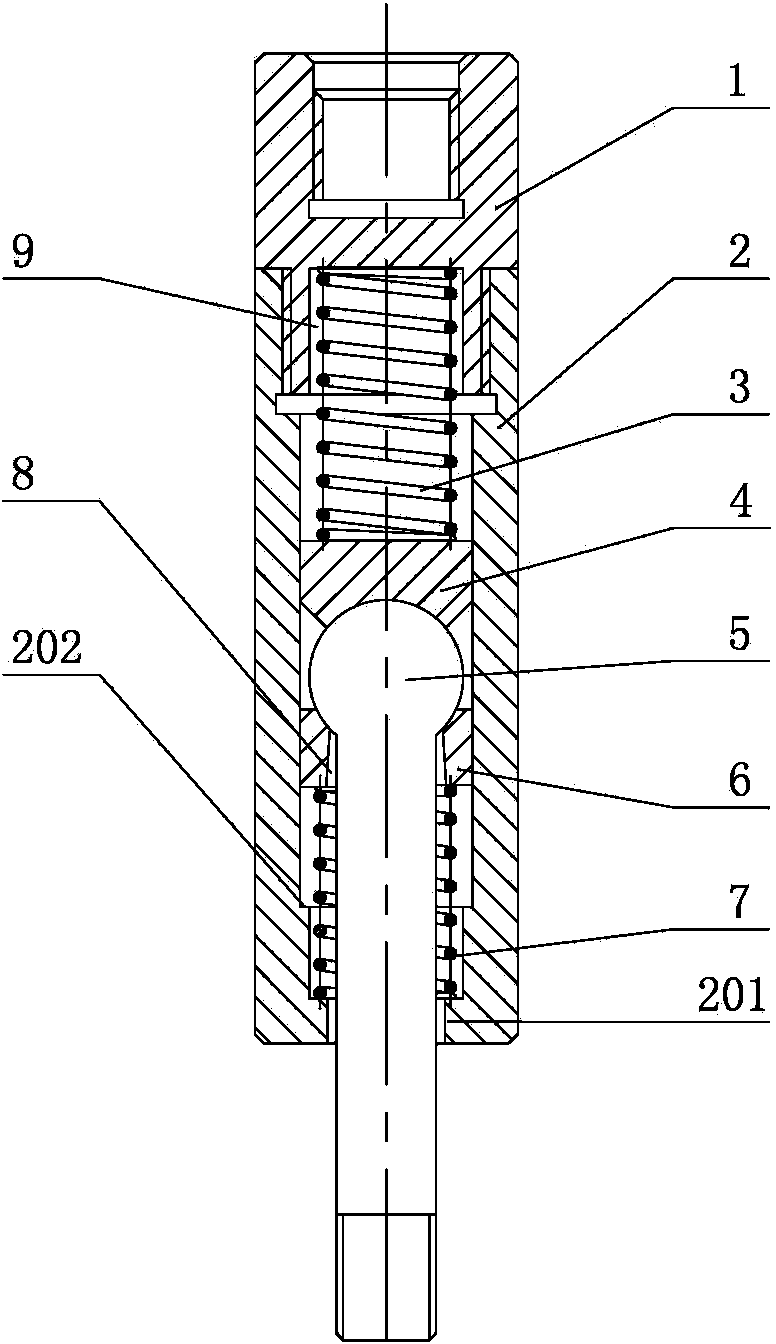
[0012] As shown in the figure, it is a sucker rod rotating shock-absorbing and anti-off device. Its body 2 is cylindrical. The center of the body 2 is provided with a through hole that penetrates the body 2 up and down. The lower ball seat 6 and the upper ball are arranged in the through hole. The seat 4, the upper ball seat 4 and the lower ball seat 6 are equipped with a ball screw 5, and the screw end of the ball screw 5 passes downward through the lower ball seat 6 and protrudes from the bottom of the through hole; the opening position of the upper end of the body 2 The upper joint 1 is connected with the internal thread, and the upper ball seat 4 and the lower ball seat 6 are slidably arranged in the through hole. A pre-compressed upper spring 3 is provided in the closed cavity between the upper end of the upper ball seat 4 and the upper joint 1. The cavity where the spring 3 is located can be a closed cavity; the lower opening of the through hole is provided with an inward...


PUM


Abstract

The invention discloses a sucker rod rotating shock-absorbing anti-releasing device in the field of a sucker rod connecting device. The sucker rod rotating shock-absorbing anti-releasing device comprises a cylindrical body, wherein a through hole vertically penetrating through the body is formed in the center of the body; a lower ball seat and an upper ball seat are arranged in the through hole; a ball head screw rod is arranged between the upper ball seat and the lower ball seat in a matched way; the screw rod end of the ball head screw rod downwards penetrates through the lower ball seat and extends out from the bottom of the through hole; the upper end opening position of the body is connected with an upper joint through internal screw threads; the upper ball seat and the lower ball seat are glidingly arranged in the through hole; and a pre-compressed upper spring is arranged in a sealed cavity formed between the upper end of the upper ball seat and the upper joint; a lower opening of the through hole is provided with an inwards projected inner step; and a pre-compressed lower spring is arranged between the lower ball seat and the inner end surface of the inner step. According to the sucker rod rotating shock-absorbing anti-releasing device, the ball head screw rod and the body can realize free rotation and swinging; the upper spring and the lower spring have a buffer shock-absorbing function; the vibration and the torsional force generated by a sucker rod due to alternate loads can be eliminated; and the eccentric wearing, releasing and fracture of the sucker rod can be prevented.

Description

technical field [0001] The invention relates to a rod pump oil production equipment in an oil field, in particular to a sucker rod connecting device. Background technique [0002] In the prior art, there is a ball-hinged sucker rod detachment prevention connection device, its publication number is: CN203570218U, and its publication date is: 2014-04-30. The device includes a body, and the center of the body is provided with a stepped hole that runs through the body up and down. , the upper aperture of the stepped hole is larger than the lower aperture, and the bottom of the stepped hole is provided with a lower ball seat; the lower ball seat is equipped with a ball screw, and the screw end of the ball screw extends downward through the lower ball seat and protrudes from the bottom of the stepped hole. And it is connected with the transition joint, an upper ball seat matched with the ball end of the ball screw is arranged in the stepped hole, and the upper ball seat is threade...

Claims


Application Information

Patent Timeline
IPC IPC(8): E21B17/02
Inventor 杨国富刘国军
Owner 济源市石油机械有限公司
Learn More