Foam pipe rheological test system and application thereof

A testing system and foam tube technology, applied in the direction of flow characteristics, measuring devices, instruments, etc., can solve the problem of not considering the influence of tube diameter, etc., and achieve the effect of improving pressure resistance performance

Active Publication Date: 2014-09-10
CHINA UNIV OF PETROLEUM (EAST CHINA)
View PDF3 Cites 5 Cited by
  • Summary
  • Abstract
  • Description
  • Claims
  • Application Information

AI Technical Summary

Problems solved by technology

However, this experiment did not consider the effect of pipe diameter on rheology, nor did it combine rheology with foam sand-carrying law

Method used


Image

  • Foam pipe rheological test system and application thereof
  • Foam pipe rheological test system and application thereof
  • Foam pipe rheological test system and application thereof

Examples


Embodiment 1

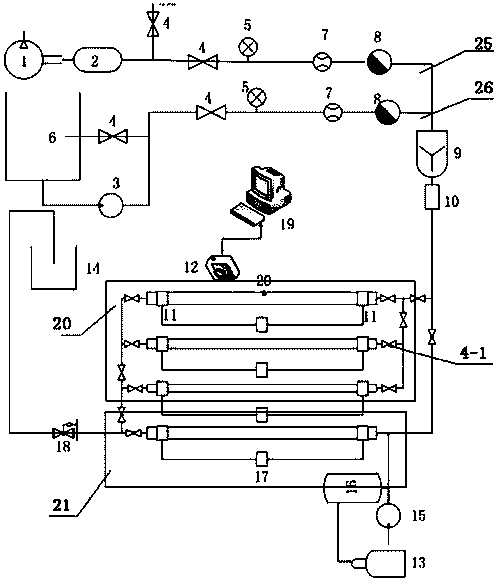
[0041] A foam tube rheological test system, the system includes a foam generator, a foam fluid test group pipe 20 and a foam sand-carrying fluid test pipe 21 respectively connected to the foam generator, in the foam fluid test group pipe 20 and The liquid outlet end of the foamy sand-carrying fluid test tube 21 is connected with a sedimentation tank 14; the liquid inlet of the foamy sand-carrying fluid test tube 21 is connected with a sand adding device; A plurality of foam fluid test tubes, a valve 4-1 is arranged on the pipeline connecting multiple foam fluid test tubes, and a single branch connection of a single foam fluid test tube is realized by opening and closing the valves 4-1 at different positions of the above pipelines into the foam generator, multiple foam fluid test tubes connected in parallel to the foam generator or multiple foam fluid test tubes connected in series to the foam generator.

[0042] Described foam generator comprises gas pipeline 25 and foam gener...

Embodiment 2

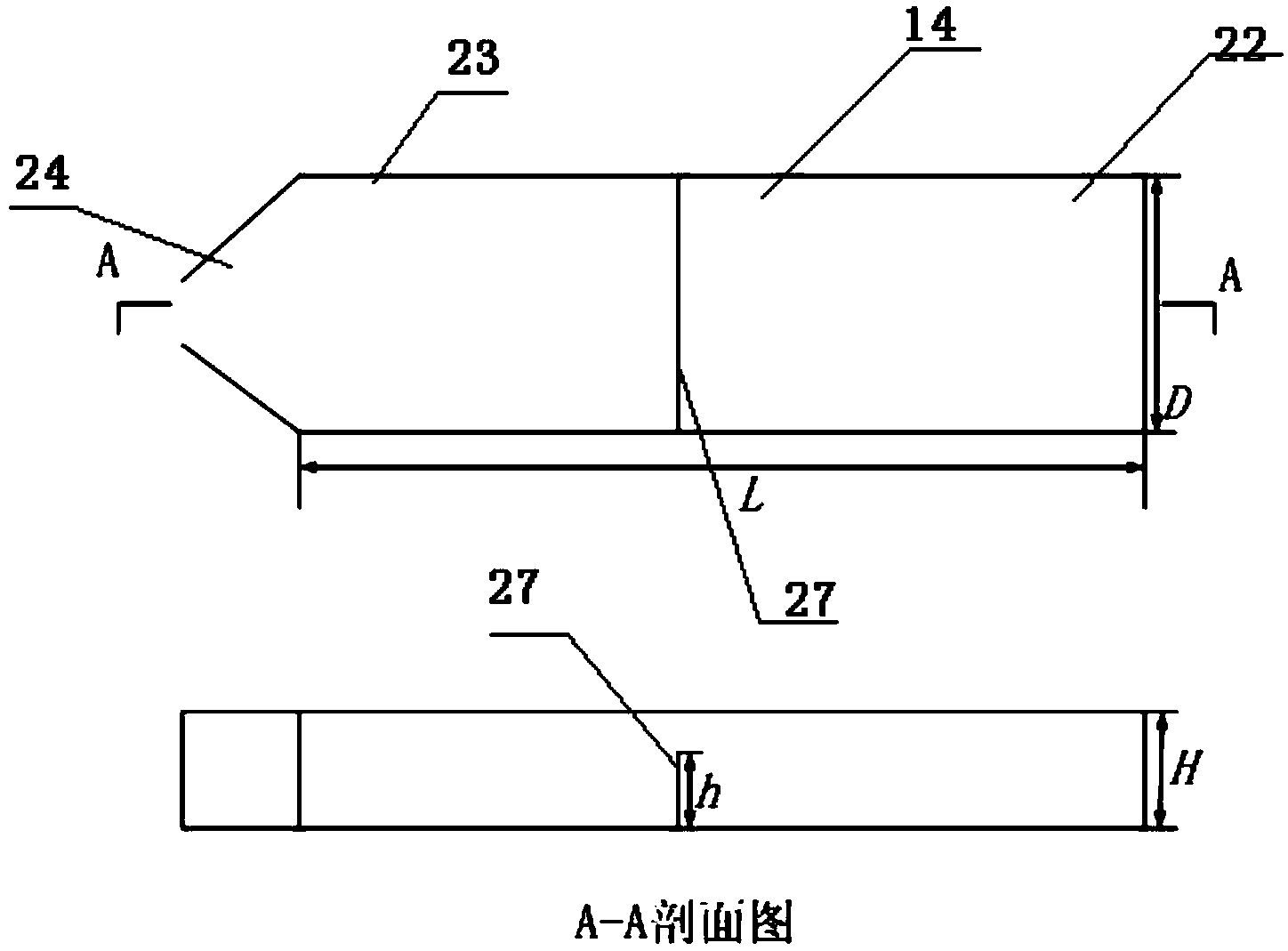
[0049] A foam tube rheological test system as described in Example 1, the difference is that the settling tank 14 is provided with two-stage settling tanks sequentially from the flow direction of the waste liquid, namely the primary settling tank 22 and the secondary settling tank 23 , the drain port 24 of the secondary sedimentation tank 23 is trapezoidal.

Embodiment 3

[0051] A kind of foam tube rheological test system as described in embodiment 1, its difference is that, the height of described boundary plate 27 is 2 / 3 of the height of sedimentation tank 14, and the width of sedimentation tank 14 is 2 / 3 of the foam fluid test group tube outlet. The diameter of the liquid port and the liquid outlet of the foam-carrying fluid test tube is 8-12 times, and the length of the sedimentation tank is 2-8 times its width. The bottoms of the primary sedimentation tank and the secondary sedimentation tank are provided with folded structures.


PUM


Abstract

The invention discloses a foam pipe rheological test system which comprises a foam generator, and a foam fluid test group pipe and a foam sand-containing fluid test pipe which are respectively connected with the foam generator, wherein the liquid outlet ends of the foam fluid test group pipe and the foam sand-containing fluid test pipe are connected with a settling tank; a liquid inlet of the foam sand-containing fluid test pipe is connected with a sand adding device; the foam fluid test group pipe comprises a plurality of foam fluid test pipes which are connected in parallel through pipelines; valves are arranged on the pipelines connected with the multiple foam fluid test pipes; the single foam fluid test pipe is connected to the foam generator, the multiple foam fluid test pipes are connected in parallel to the foam generator or the multiple foam fluid test pipes are connected in series to the foam generator by switching on and off the valves at different positions of the pipelines. According to the system, the foam rheological test system and a sand adding test system are combined together, so that switching of the two systems is conveniently and quickly realized by switching off the valves.

Description

technical field [0001] The invention relates to a foam tube rheological test system and its application, belonging to the technical field of oil exploration test equipment. Background technique [0002] Foam fluid has the advantages of adjustable density, high viscosity, low density, and strong sand-carrying ability. It is more and more widely used in the petroleum industry. Therefore, the research on the rheology of foam fluid and its sand-carrying law is more and more important. The traditional method of studying the rheology of foam fluid is mostly to use rotational viscometer to statically study the rheology of foam fluid. Foam fluid is a gas-liquid two-phase flow, and the rheology will change greatly during the flow process, so tube flow must be used. The rheology of the foam can be truly reflected by the rheometer. The pipe diameter and flow rate are important factors affecting the rheology of the foam. The pipe diameter and flow rate directly affect the flow rate of t...

Claims


Application Information

Patent Timeline
Patent Type & Authority Applications(China)
IPC IPC(8): G01N11/00
Inventor 黄善波李兆敏贾祯李松岩李宾飞吕其超田帅罗璇
Owner CHINA UNIV OF PETROLEUM (EAST CHINA)
Why Eureka
Try Eureka