Connector structure used in highly integrated flip-chip cob light sources

A highly integrated, connector technology, used in connections, electrical components, conductive connections, etc., can solve the problems of shortening the service life of highly integrated flip-chip COB light sources, consuming a lot of time and labor costs, and reducing production efficiency. Conductive insulation separation effect, convenient disassembly and assembly, and the effect of improving production efficiency

Active Publication Date: 2017-03-22
深圳市格天光电有限公司
View PDF5 Cites 0 Cited by
  • Summary
  • Abstract
  • Description
  • Claims
  • Application Information

AI Technical Summary

Problems solved by technology

[0002] At present, most of the highly integrated flip-chip COB light source products on the market need to solder the power leads from the positive and negative pins, and then manually weld the power leads with an electric soldering iron. The operation of the electric soldering iron welding process is extremely cumbersome. It takes a lot of time and labor costs, which reduces production efficiency and increases production costs. In addition, the products obtained by this welding method have defects such as unreliable welding points, easy to fall off, and difficult to maintain. Service life of flip chip COB light source

Method used


Image

  • Connector structure used in highly integrated flip-chip cob light sources
  • Connector structure used in highly integrated flip-chip cob light sources

Examples


Embodiment Construction

[0020] In order to express the present invention more clearly, the present invention will be further described below with reference to the accompanying drawings.

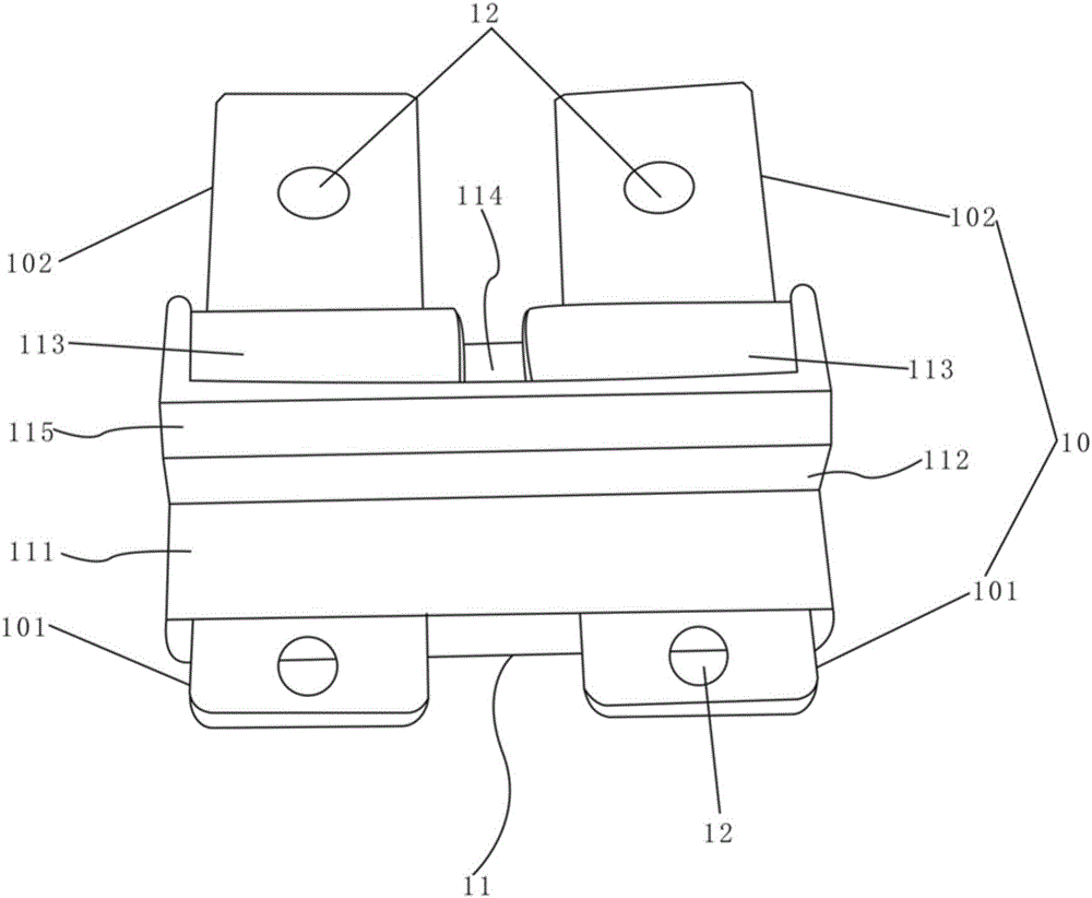
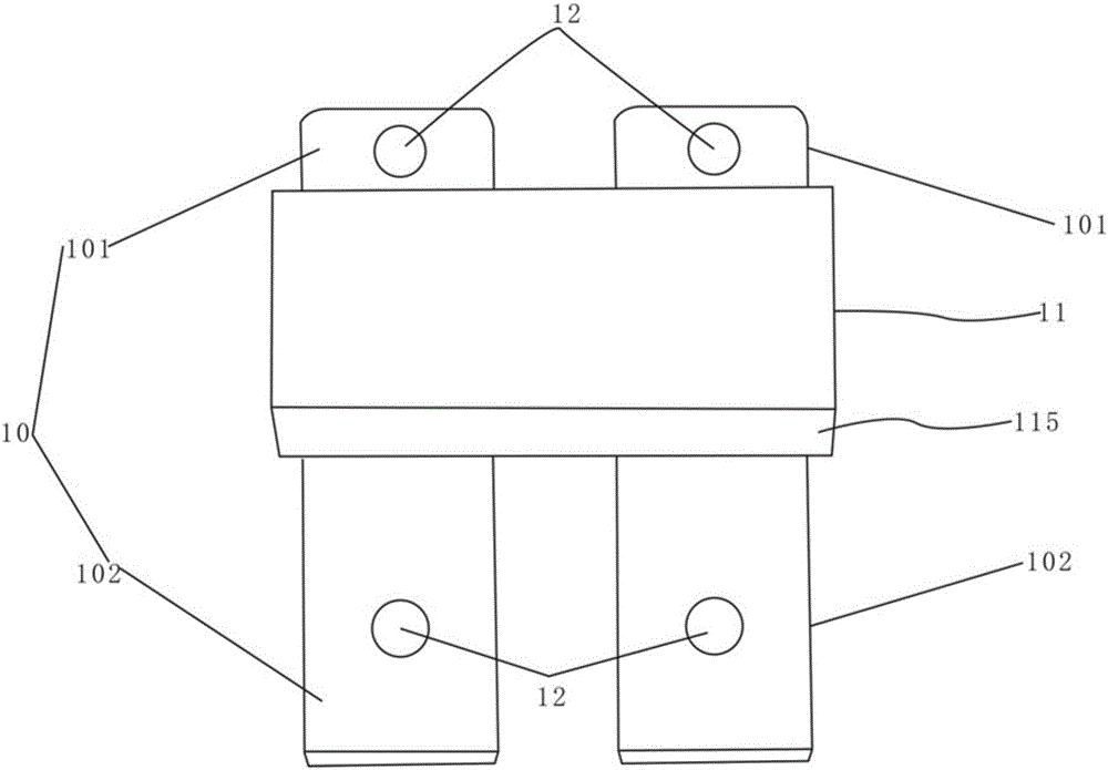
[0021] see Figure 1-2 , the connector structure used in the highly integrated flip-chip COB light source of the present invention includes two metal contact inserts 10 and an insulator 11, the two metal contact inserts 10 are respectively positive metal contact inserts and negative metal contact inserts The middle parts of the two metal contact inserts 10 are injected into the insulator 11, the front ends of the two metal contact inserts 10 form a welding portion 101 that is closely abutted with the heat dissipation substrate, and the rear ends of the two metal contact inserts 10 are formed The plug portion 102 electrically connected to the external power supply; the insulator 11 is provided with a horizontal insulating contact surface 111 and a vertical insulating contact surface 112 that are perpendicular to each...


PUM


Abstract

The invention discloses a connector structure used for a high-integration flip-chip COB light source. The connector structure includes two metal contact insertion sheets and an insulator; middle portions of the two metal contact insertion sheets are arranged in the insulator in an injection molding mode; the front ends of the two metal contact insertion sheets form welding portions which abut against a heat dissipation substrate; the rear ends of the two metal contact insertion sheets form insertion portions which are electrically connected with an external power source; one surface of the insulator is provided with a horizontal insulation contact surface and a vertical insulation contact surface which are perpendicular to each other; the horizontal insulation contact surface and the middle portions of the two metal contact insertion sheets are subjected to injection molding; and one surface of the insulator is provided with a plurality of sink stages which can ensure insertion strength. According to the connector structure used for the high-integration flip-chip COB light source, the two metal contact insertion sheets and the insulator are molded through injection molding, and are combined tightly and firmly, and have an excellent conductive insulation separation effect; the front ends of the metal contact insertion sheets only expose the welding portions which abut against the heat dissipation substrate, and therefore, the problem of short circuiting of the light source, which is caused by tin sweat overflow when the connector is welded to heat dissipation substrate can be avoided.

Description

technical field [0001] The invention relates to the field of lighting equipment, in particular to a connector structure used in a highly integrated flip chip COB light source. Background technique [0002] At present, most of the high-integrated flip chip COB light source products on the market need to weld the power leads from the positive and negative pins, and then manually weld the power leads with an electric soldering iron. It takes a lot of time and labor costs, which reduces the production efficiency and increases the production cost; in addition, the products obtained by this welding method have defects such as unstable welding points, easy to fall off, and difficult maintenance, thus shortening the high integration Lifespan of flip-chip COB light sources. SUMMARY OF THE INVENTION [0003] In view of the deficiencies in the above technologies, the present invention provides a connector structure for a highly integrated flip-chip COB light source with stable struc...

Claims


Application Information

Patent Timeline
Patent Type & Authority Patents(China)
IPC IPC(8): H01R11/07
Inventor 王志成
Owner 深圳市格天光电有限公司
Why Eureka
Try Eureka