Suspended glass insulator chain lifting clamp

A technology of glass insulators and fixtures, which is applied in transportation and packaging, load hanging components, overhead line/cable equipment, etc. The effect of reducing manufacturing materials and costs

Active Publication Date: 2014-09-10
STATE GRID SICHUAN ELECTRIC POWER
View PDF4 Cites 7 Cited by
  • Summary
  • Abstract
  • Description
  • Claims
  • Application Information

AI Technical Summary

Problems solved by technology

[0004] In the prior art, clamps are usually used to clamp the lower end of the insulator string to lift the hanging glass insulator string to the overhead line, and it is easy to shake left and right in the air during the lifting process, which is difficult to control

Method used


Image

  • Suspended glass insulator chain lifting clamp
  • Suspended glass insulator chain lifting clamp

Examples


Embodiment 1

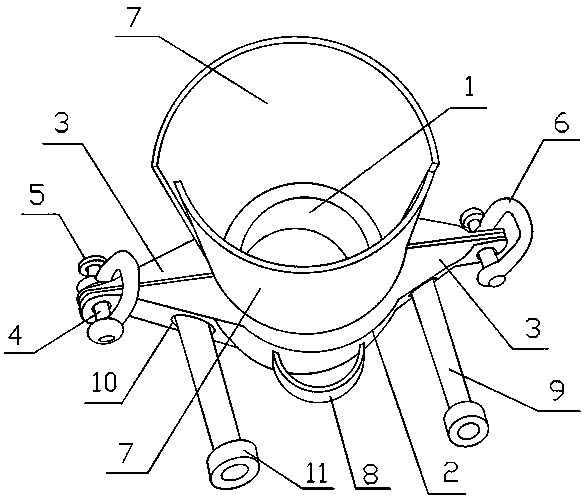
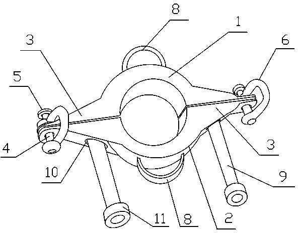
[0023] Such as figure 1 and figure 2 As shown, the hanging glass insulator string lifting jig includes a first jig 1 and a second jig 2. Both the first jig 1 and the second jig 2 are in the shape of a semicircle, that is, the center has a semicircular hollow structure. A fixture 1 and a second fixture 2 are installed together in the manner that two semicircular hollow structures are adjacent to each other, so that the two semicircular hollow structures form a circular mounting hole for fixing a string of hanging glass insulators; the first fixture Both ends of the fixture 1 and the second fixture 2 are bent outwards, and a mounting ear 3 is formed at both ends of the first fixture 1 and the second fixture 2, a total of 4 mounting ears 3, the first fixture 1 The mounting ear 3 corresponding to the second clamp 2 is movably connected by the connecting shaft 4, that is, the mounting ear 3 can slide left and right on the connecting shaft 4 (the mounting ear 3 is slidably connect...

Embodiment 2

[0027] On the basis of Embodiment 1, the hanging glass insulator string lifting fixture in this embodiment, the two mounting ears 3 of the first fixture 1 are also provided with a limit rod 9 on the side facing the second fixture 2, The two mounting ears 3 of the second fixture 2 are provided with a through hole 10 corresponding to the size and position of the limit rod 9, the limit rod 9 is passed through the through hole 10, and the end of the limit rod 9 The threaded connection has a limit nut 11. In this embodiment, setting the limit rod 9 is mainly to keep the first clamp 1 and the second clamp 2 on the same horizontal plane, and further strengthen the stability of the first clamp 1 and the second clamp 2 on the horizontal plane.

Embodiment 3

[0029] On the basis of Embodiment 1 or Embodiment 2, in this embodiment, the coaming plate 7 is set as a hollow structure to reduce the weight of the entire lifting fixture, so that it is more labor-saving when lifting the insulator string. Open a plurality of through holes, the shape and size of the through holes are not limited, as long as the strength of the back panel 7 after opening the through holes can still limit the position of the insulator string.


PUM


Abstract

The invention discloses a suspended glass insulator chain lifting clamp. The suspended glass insulator chain lifting clamp comprises a semi-circular first clamp body and a semi-circular second clamp body, two ends of each of the first clamp body and the second clamp body are bent outwards to form mounting lugs, corresponding mounting lugs of the first clamp body and the second clamp body are movably connected via connection shafts, U-shaped lifting lugs are arranged on the connection shafts, a surrounding plate which is a curved plate with the radius gradually increasing from bottom top is arranged at the upper end of each of the first clamp body and the second clamp body, and a fixing ring is arranged on the outer circumferential face of each of the first clamp body and the second clamp body. Since the surrounding plates and the fixing rings capable of connecting fixing ropes are arranged on the lifting clamp, the suspended glass insulator chain lifting clamp can be prevented from inclining upwards by the surrounding plates, the integral lifting clamp and insulator chains on the lifting clamp can be prevented from swaying in the air by the two fixing rings, the insulator chains can be fed in to the air stably and quickly, and the suspended glass insulator chain lifting clamp has the advantages of simple and compact structure, convenience in use, low in cost and the like.

Description

[0001] technical field [0002] The invention relates to the technical field of electric power construction, in particular to a lifting jig for hanging glass insulator strings. Background technique [0003] The insulator is the main body of power transmission line insulation. Its purpose is to suspend the wire and keep the wire insulated from the tower and the earth. It should have high mechanical strength, good insulation performance, not be affected by sharp changes in strength, and resist natural erosion and aging. features. The material of the insulator generally adopts porcelain and toughened glass, and synthetic materials are also useful. Suspension insulators are often assembled into strings in transmission lines with a voltage level of 35KV and above. Suspension insulators generally form insulator strings and are used on lines with different voltage levels. At present, the insulators produced in my country are divided into two types: ordinary type and anti-pollutio...

Claims


Application Information

Patent Timeline
Patent Type & Authority Applications(China)
IPC IPC(8): H02G1/02B66C1/42B66C13/08
Inventor 李建峰黎懿
Owner STATE GRID SICHUAN ELECTRIC POWER
Why Eureka
Try Eureka