Heat dissipation module

A heat dissipation module and heat dissipation layer technology, which is applied in the field of heat dissipation modules, can solve the problems of complex heat dissipation device design and overall setting, increase process and operation time, increase time and cost, etc., to improve space utilization, increase installation space, The effect of good cooling effect

Inactive Publication Date: 2014-09-10
DELTA ELECTRONICS INC
View PDF7 Cites 2 Cited by
  • Summary
  • Abstract
  • Description
  • Claims
  • Application Information

AI Technical Summary

Problems solved by technology

However, it is time-consuming to dispose the heat dissipation devices on the motherboard with complex power components or the circuit board with complex circuits, and the heat dissipation effect is limited, especially in devices with a large number of components or more complex devices. It is necessary to consider the installation space and heat dissipation effect at the same time. The design and overall configuration of the heat dissipation device will be more complicated, which will inevitably increase the time and cost of the overall process.
On the other hand, most of the existing connection methods between heating elements and heat sinks are screw locks. However, this connection method will increase the process and work time, and the number of components contained in it is large, and there will be problems that are not easy to automate.

Method used


Image

  • Heat dissipation module
  • Heat dissipation module
  • Heat dissipation module

Examples


Embodiment Construction

[0041] A heat dissipation module according to a preferred embodiment of the present invention will be described below with reference to related drawings, wherein the same components will be described with the same reference symbols.

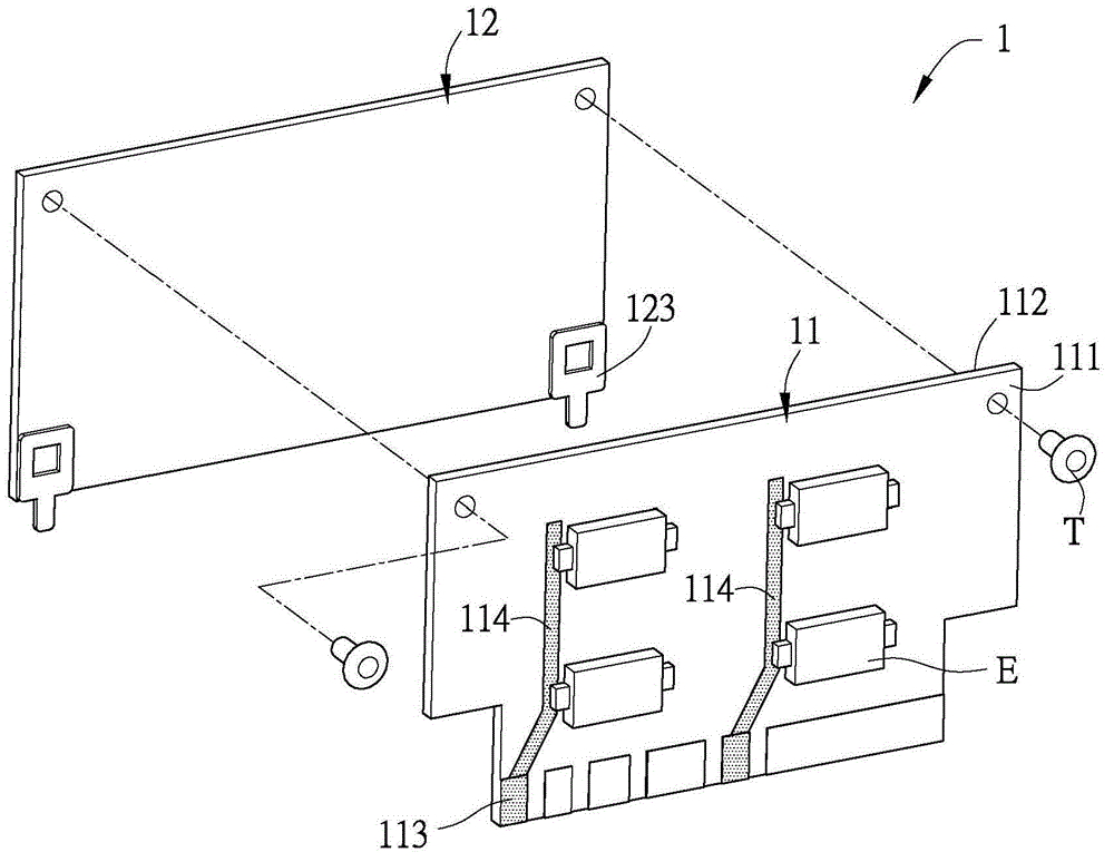
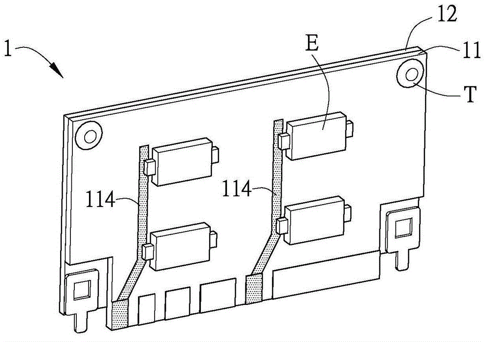
[0042] Figure 1A It is an exploded schematic diagram of a heat dissipation module in a preferred embodiment of the present invention, Figure 1B for Figure 1A A combined schematic diagram of a cooling module. Please also refer to Figure 1A and Figure 1B As shown, the heat dissipation module 1 includes at least one substrate 11 and a heat dissipation layer 12 , wherein the heat dissipation module 1 is vertically arranged on a main board (not shown). In detail, the cooling module 1 is installed on the main board through pin through hole (PTH) or surface mount technology (SMT), and the "main board" referred to here can be a main board. This is not limited. However, the above-mentioned connection methods are understood by those with ordinary k...


PUM


Abstract

A heat dissipation module comprises a substrate and a heat dissipation layer. The substrate has a first surface and a second surface. The heat dissipation layer is arranged on the second surface. At least one heating element is electrically connected to the first surface, and the heat dissipation module is vertically arranged on a motherboard. By adopting the heat dissipation module of the invention, hours required in the heat dissipation process can be saved, the efficiency of automated production can be improved, the assembly cost can be reduced, and an effect of high heat dissipation efficiency can be achieved.

Description

technical field [0001] The present invention relates to a heat dissipation module, in particular to a heat dissipation module which can save assembly space and improve heat dissipation effect. Background technique [0002] With the development of the electronic industry, the requirements for the operation speed and effect of electronic components are increasing day by day. However, the heat dissipation problems derived from it are becoming more and more serious, which in turn affects the performance and stability during operation, and at least causes the performance of electronic devices to deteriorate. , it will lead to burning of electronic devices. In order to enable the electronic device to operate normally, a heat sink is generally installed on the heat-generating electronic components, and the heat energy is exported through the heat sink. [0003] In recent years, due to the advancement of technology, the volume of electronic devices has gradually shrunk for portabil...

Claims


Application Information

Patent Timeline
Patent Type & Authority Applications(China)
IPC IPC(8): H05K7/20
Inventor 陈鸿川许正纬
Owner DELTA ELECTRONICS INC
Why Eureka
Try Eureka