Implant specific drill bit

A technology of drill bits and implants, applied in the field of orthopedic surgery drill bits, can solve problems such as damaged cartilage

Active Publication Date: 2014-09-10
EPISURF IP MANAGEMENT
View PDF7 Cites 4 Cited by
  • Summary
  • Abstract
  • Description
  • Claims
  • Application Information

AI Technical Summary

Problems solved by technology

[0010] A general object of the present invention is to solve the problem of the design of an improved instrument for use in the replacement of damaged cartilage

Method used


Image

  • Implant specific drill bit
  • Implant specific drill bit
  • Implant specific drill bit

Examples


Embodiment Construction

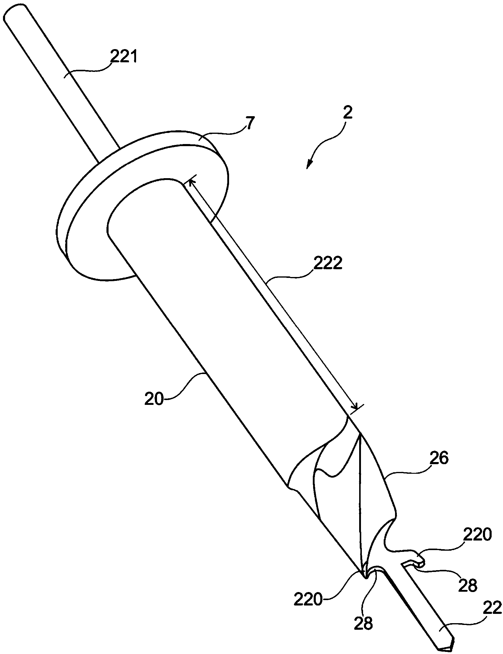
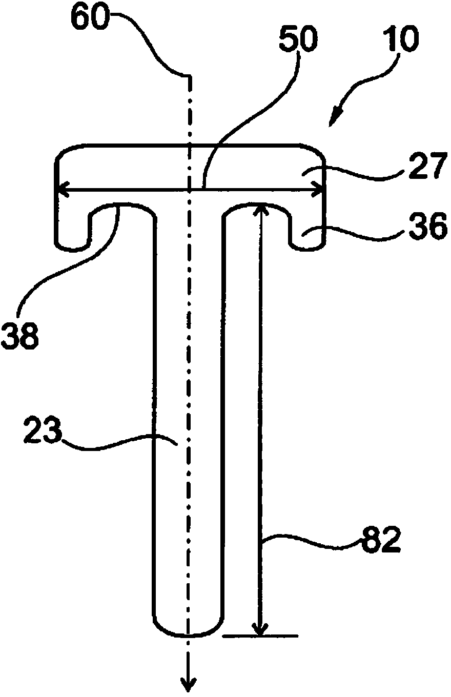
[0049] See figure 1 -4. The present invention discloses a special drill bit 2 for implantation, which is a combination of a drill and a bone remover, and is used to drill a recess, a hole or a bone cavity in the bone at the site of cartilage damage, such as in in one joint of one patient. The manufactured pocket is the same size and shape as the implant, or slightly smaller than the implant, and is intended for fastening and / or implanting the implant by compression. See Figure 2b , 4b According to the present invention, a suitable implant 10 to be implanted includes an extension post 23 and an implant body 27, and see image 3 , in the bone tissue 32 and the cartilage tissue 34 in the joint, the implant 10 is embedded in a pocket formed by using the implant-specific drill 2 according to the present invention.

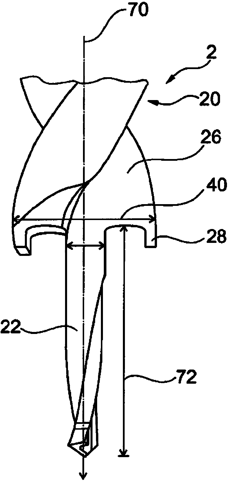
[0050] like figure 1 As shown, the implant specific drill 2 according to the present invention includes a drill and bone remover body 20 , a central drill portion...


PUM


Abstract

The present invention provides a design method designing an implant specific drill bit comprising steps; e. determining or selecting a size and shape of an orthopedic implant comprising a circular shaped implant body and a centrally placed circular shaped extending post protruding from the bone contacting surface in a longitudinal y-axis direction of the implant; and f. selecting design parameters for the implant specific drill bit by; - selecting the width of the broadest part of the bone remover in a side view to correspond to, or to be slightly smaller than, the diameter of the implant body of the specific implant that is to be implanted; - selecting the rotational volume and the length of the central drill part to correspond to, or to be slightly smaller than, the diameter of the extending post of the specific implant that is to be implanted; ; -selecting the curvature of the cutting edge that is placed anywhere peripherally around or surrounding the central drill part of the implant specific drill bit to correspond to the curvature of the bone contacting surface of the implant.

Description

technical field [0001] The field of the invention relates to orthopedic drills for forming bone cavities. Background technique [0002] general background [0003] Pain in the joints and overuse of the body is a common problem. The weight-bearing and articulating surfaces of the knee, as well as other joints, are covered with a layer of soft tissue, usually consisting of a large amount of hyaline cartilage. There is very little friction between the surrounding parts of the joint and the cartilage, facilitating joint movement under high stress. However, cartilage is easily damaged due to disease, damage, or long-term wear and tear. Furthermore, cartilage does not heal easily when damaged compared to other connective tissues, and when it does heal, the durable hyaline cartilage is often replaced by less durable fibrocartilage. This means that the damage to the cartilage gets progressively worse. As injury / illness is accompanied by pain as a problem, it will lead to disabi...

Claims


Application Information

Patent Timeline
Patent Type & Authority Applications(China)
IPC IPC(8): A61B17/17A61F2/46A61B17/16A61F2/30A61F2/38
CPCA61B2019/304A61F2/3872A61B17/1615A61B2019/307A61F2/30942A61F2002/4687A61B2019/508A61F2/4618A61B2017/0046A61B17/1675A61B17/1764A61F2/30756A61B17/1637A61F2002/30948A61B2017/568A61B2019/462A61F2002/4662A61B2019/306A61F2/4684A61F2002/30759A61B2034/108A61B2090/034A61B2090/036A61B2090/037A61B2090/062A61B17/17A61B17/1739
Inventor 尼娜·巴克卡琳·韦尔梅林
Owner EPISURF IP MANAGEMENT
Why Eureka
Try Eureka