
Floating front ring

A technology of transmission system and lateral movement, applied in the field of transmission system, can solve problems such as reducing power transmission efficiency, and achieve the effect of eliminating angular displacement

Inactive Publication Date: 2014-09-10
PAHA DESIGNS
View PDF4 Cites 8 Cited by
  • Summary
  • Abstract
  • Description
  • Claims
  • Application Information

AI Technical Summary

Problems solved by technology

These two conditions lead to unnecessary friction on the entire bicycle drive train
Understandably, this increased friction reduces the efficiency of power transfer from the rider to the wheels

Method used


Image

  • Floating front ring
  • Floating front ring
  • Floating front ring

Examples


Embodiment Construction

[0038] The ensuing description provides examples only, and is not intended to limit the scope, applicability, or configuration of the claims. Rather, the ensuing description will provide those skilled in the art with an enabling description for implementing the described embodiments. It being understood that various changes may be made in the function and arrangement of elements without departing from the spirit and scope of the appended claims.

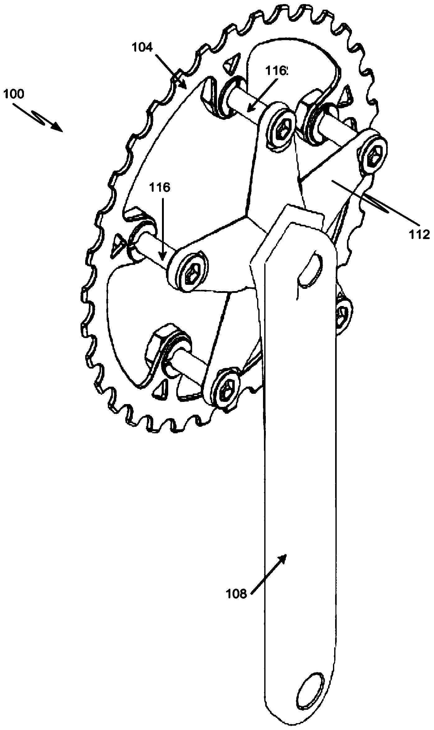
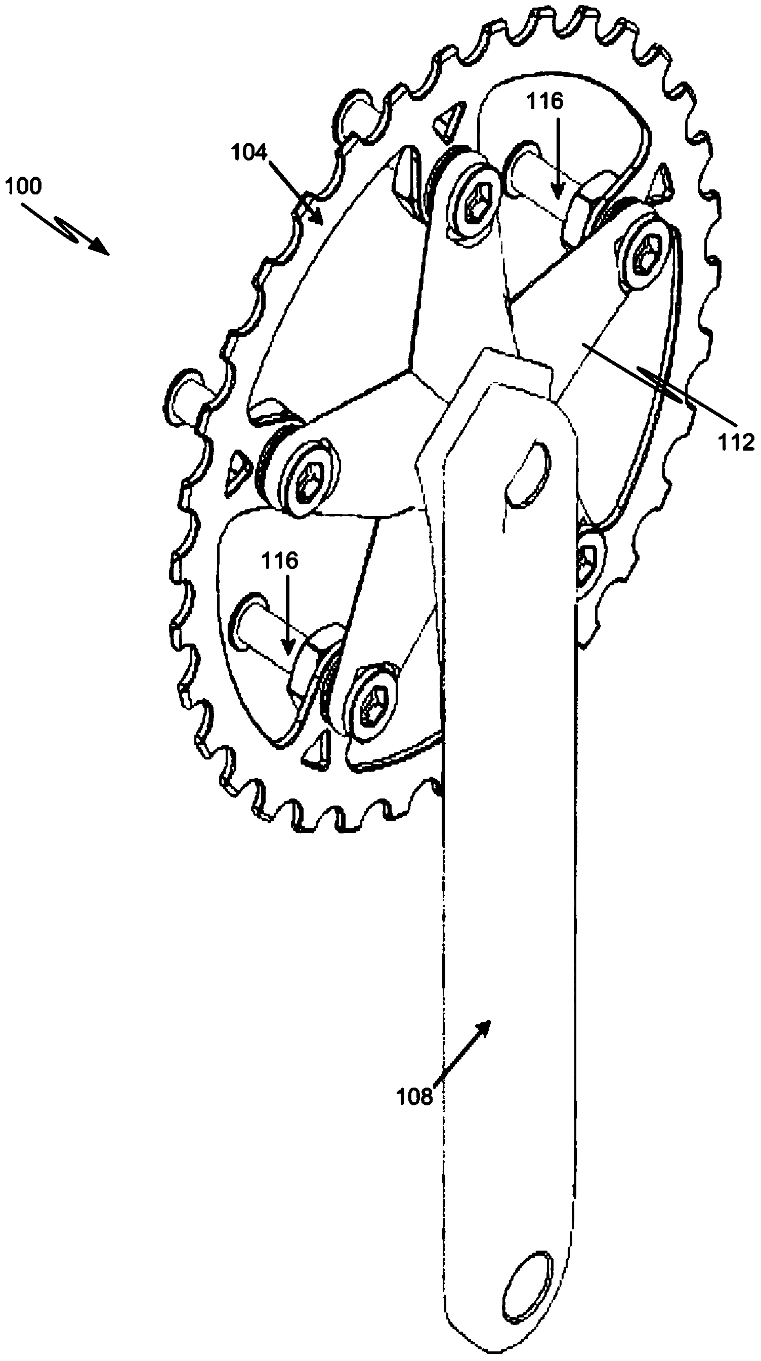
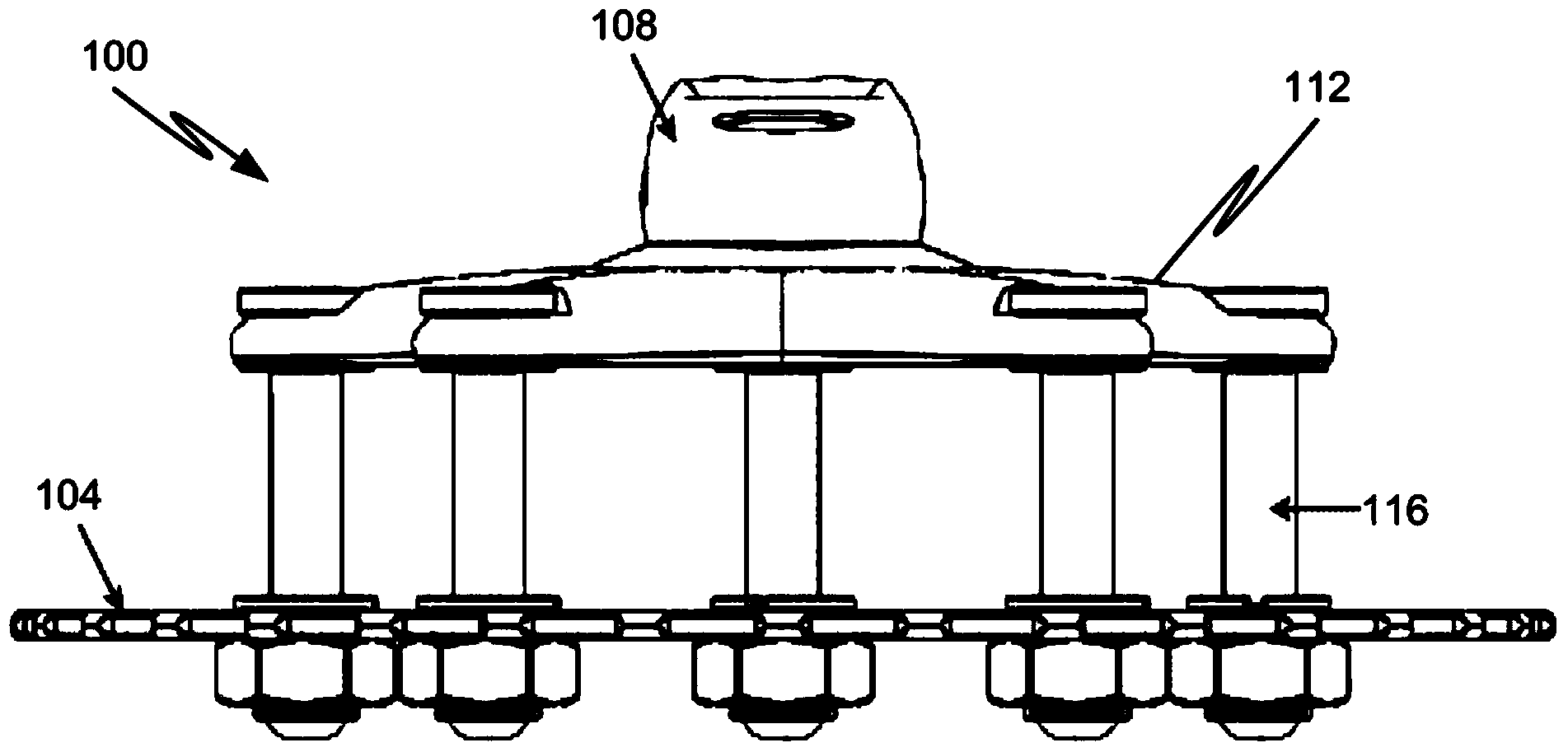
[0039] First refer to Figure 1-6B , a first embodiment of the crankset 100 used in a bicycle transmission system will be described. The features of the crankset 100 described herein may be included in any other crankset design without departing from the scope of the present disclosure. In other words, any feature of any crank design or configuration described herein may be provided in any other crank design or configuration.

[0040] Furthermore, the crankset assemblies described herein may be manufactured using any type of known...


PUM


Abstract

A bicycle transmission system is provided herein. The bicycle transmission system includes a sprocket or ring that is capable of sliding amongst an infinite number of lateral positions relative to a crank arm. The movement of the sprocket or ring facilitates an optimal chain path from the sprocket or ring to another sprocket or ring in the transmission system and, therefore, increases the efficiency with which power is transferred through the system.

Description

technical field [0001] The present disclosure relates generally to drivetrains, and in particular, to bicycle drivetrains. Background technique [0002] Cycling is becoming an increasingly popular sport. In fact, bicycles are used for many purposes, from mountain bikes to road bikes, from single-speed commuter bikes to ultralight triathlon and time trial bikes, from cruiser bikes to downhill bikes, and more. Many advances in bicycle technology have manifested themselves in new materials for frames and components. There have also been great technological advances in the design of bicycle components such as brakes, seats, handlebars, drivetrains, etc. [0003] Most bicycle drivetrains have multiple speeds that allow the rider to select the appropriate gear ratio to suit the particular riding conditions encountered while riding. One of the most common types of drivetrain assemblies for multi-speed bicycles utilizes a chain extending between a set of front sprockets (often ca...

Claims


Application Information

Patent Timeline
Patent Type & Authority Applications(China)
IPC IPC(8): B62M9/00
CPCY10T74/2165B62M9/14B62M3/00B62M9/12F16D3/06
Inventor L.约翰逊B.米格
Owner PAHA DESIGNS
Learn More