Separation device comprising a swirler
A technology of separation device and cyclone, which is applied in the direction of cyclone device, the device whose axial direction of the swirl remains unchanged, and separation method, etc., which can solve the problems of large energy loss and large pressure drop
- Summary
- Abstract
- Description
- Claims
- Application Information
AI Technical Summary
Problems solved by technology
Method used
Image

Examples
Embodiment Construction
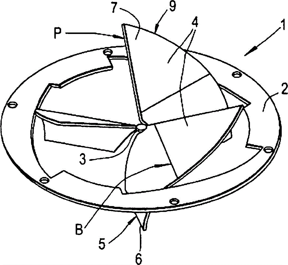
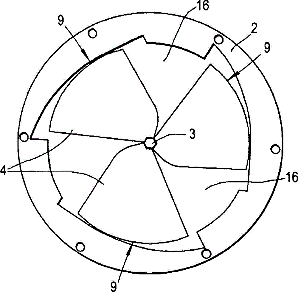
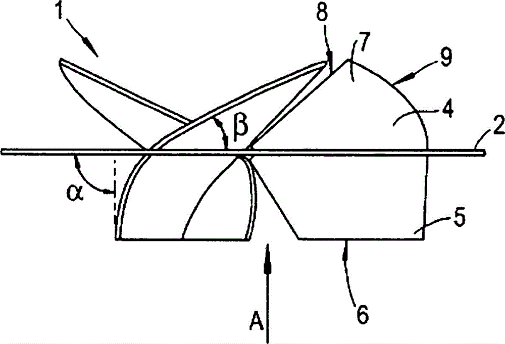
[0028] Figures 1A-1C A typical embodiment of a sheet metal swirler 1 is shown, comprising a peripheral ring 2, a central part 3 and three radially equidistant vanes 4 bridging the central part 3 and the peripheral ring 2 . The blades 4 are identical in size and shape. The vane 4 has a flow inlet portion 5 at the flow inlet side edge 6 and a flow outlet portion 7 at the flow outlet side edge 8 .
[0029] Such as Figure 1C As shown, the flow inlet portion 5 delimits an inlet angle α of approximately 90° to the plane passing through the ring 2 and the central portion 3 , said plane constituting the plane of the original sheet metal blank. The flow outlet portion 7 defines an outlet angle β of approximately 40 degrees. The flow inlet side edge 6 is truncated substantially perpendicular to the direction of flow (eg Figure 1C Indicated by the arrow A in).
[0030] In the illustrated embodiment, the flow inlet portion 5 of the vane 4 is gradually curved from having an inlet ...
PUM
 Abstract
Description
Claims
Application Information
 - R&D
- Intellectual Property
- Life Sciences
- Materials
- Tech Scout
- Unparalleled Data Quality
- Higher Quality Content
- 60% Fewer Hallucinations
Browse by: Latest US Patents, China's latest patents, Technical Efficacy Thesaurus, Application Domain, Technology Topic, Popular Technical Reports.
© 2025 PatSnap. All rights reserved.Legal|Privacy policy|Modern Slavery Act Transparency Statement|Sitemap|About US| Contact US: help@patsnap.com