Diversion-type gas-liquid separation unit, gas-liquid separation device and multi-phase flow reactor

A gas-liquid separation device and gas-liquid separation technology, which is applied in the field of diversion type gas-liquid separation unit, gas-liquid separation unit, and gas-liquid separation device, can solve the problem of excessive liquid in the purified gas, and achieve sufficient and thorough separation and discharge. Adaptable, easy-to-implement effects

Inactive Publication Date: 2014-09-17
CHNA ENERGY INVESTMENT CORP LTD +1
View PDF9 Cites 6 Cited by
  • Summary
  • Abstract
  • Description
  • Claims
  • Application Information

AI Technical Summary

Problems solved by technology

[0005] The technical problem to be solved by the present invention is to provide a diversion type gas-liquid separation unit, which can relatively effectively improve the accuracy of gas-liquid separation, thereby improving the problem of excess liquid in the purification gas in the prior art
[0006] Furthermore, the technical problem to be solved by the present invention is to provide a gas-liquid separation device and a multiphase flow reactor, which can relatively effectively improve the accuracy of gas-liquid separation, thereby improving the problem of excess liquid in the purification gas in the prior art

Method used


Image

  • Diversion-type gas-liquid separation unit, gas-liquid separation device and multi-phase flow reactor
  • Diversion-type gas-liquid separation unit, gas-liquid separation device and multi-phase flow reactor
  • Diversion-type gas-liquid separation unit, gas-liquid separation device and multi-phase flow reactor

Examples


Embodiment Construction

[0033] The specific embodiments of the present invention will be described in detail below in conjunction with the accompanying drawings. It should be understood that the specific embodiments described here are only used to illustrate and explain the present invention, and the protection scope of the present invention is not limited to the following specific embodiments. .

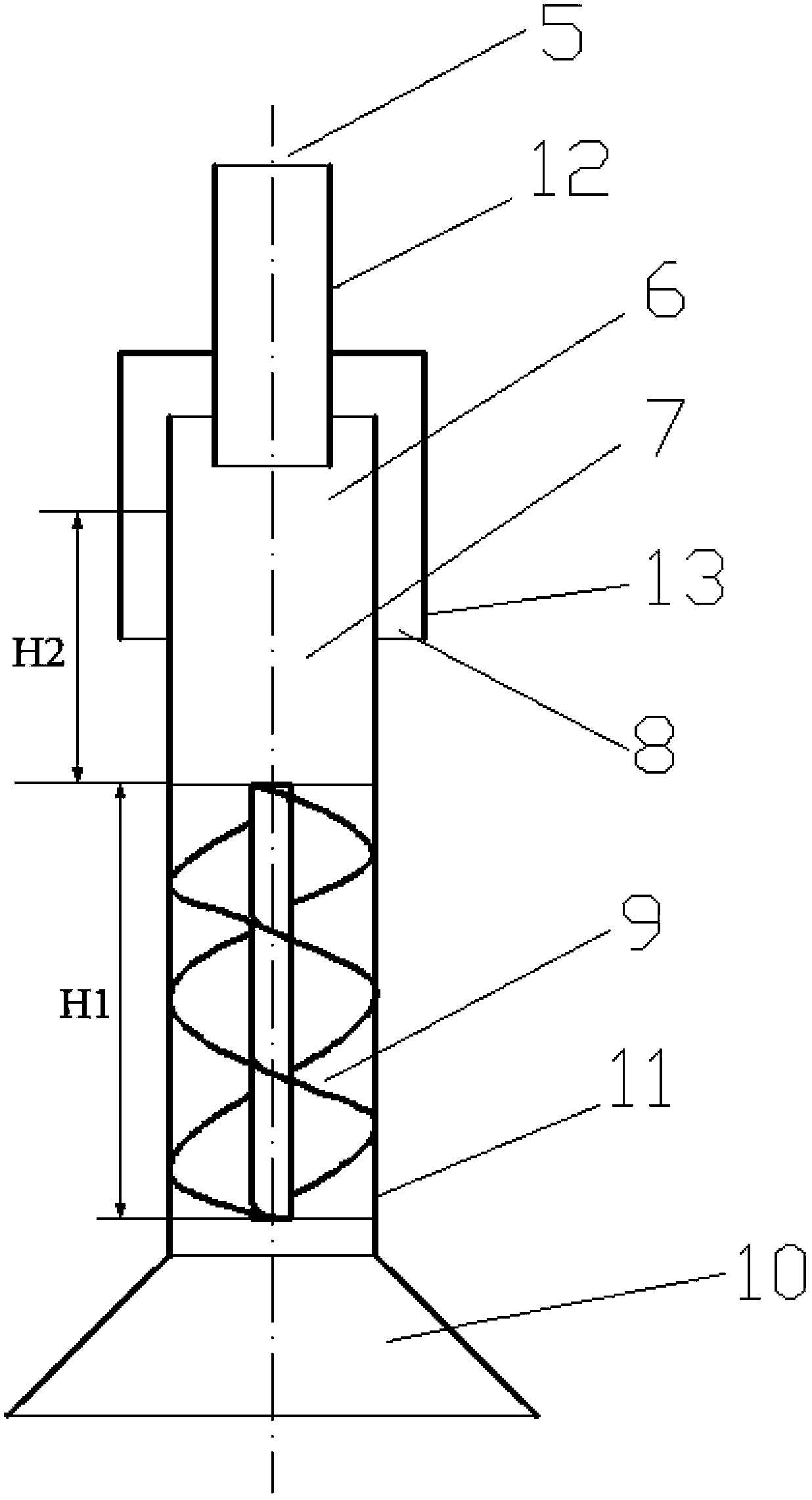
[0034] see figure 1As shown, the diversion type gas-liquid separation unit of a specific embodiment of the present invention comprises a hollow unit body, the unit body has an inlet area 10, a purified gas outlet area 5, and a gas outlet between the inlet area 10 and the purified gas outlet area 5. The liquid outlet area 8. Wherein, the internal space of the unit main body includes in turn a flow guide area 9 for receiving the gas-liquid mixture input from the inlet area 10, a liquid particle size increasing gathering area 7, and a gas-liquid separation area 6, wherein the flow guide area 9 is provided fo...


PUM

PropertyMeasurementUnit
particle diameteraaaaaaaaaa

Abstract

A diversion-type gas-liquid separation unit includes a hollow unit main body which includes an inlet zone (10), a purified gas outlet zone (5) and a liquid outlet zone (8) which is arranged therebetween. An internal space of the unit main body includes, successively, a flow guiding zone (9), a liquid particle size increasing and aggregating zone (7) and a liquid gas-liquid separation zone (6), wherein the flow guiding zone (9) is used for receiving a gas-liquid mixture from the inlet zone (10) and forming an eddy flow, and the liquid gas-liquid separation zone (6) is used for outputting purified gas and separated liquid. The liquid particle size increasing and aggregating zone (7) has a preset through-flow length so that a liquid membrane is formed on an inner wall surface of the liquid particle size increasing and aggregating zone (7) through a centrifugal force generated by the eddy-flow gas-liquid mixture. In addition, the invention also provides a gas-liquid separation device and a multi-phase flow reactor. The gas-liquid separation unit has relative high separation accuracy and separation efficiency when liquid is separated from gas, is simple in structure, is easy to carry out and is strong in adaptability.

Description

technical field [0001] The invention relates to a gas-liquid separation component, in particular to a flow-guided gas-liquid separation unit for separating liquid from a gas-liquid mixture. Further, the present invention relates to a gas-liquid separation device comprising the flow-guiding gas-liquid separation unit. In addition, the present invention also relates to a gas-liquid separation unit comprising the gas-liquid separation device. Background technique [0002] Due to the requirements on the dryness of the gas during work, some links in the fluid treatment system (such as multiphase flow reactors, etc.) need to use a gas-liquid separation device to separate the liquid or slurry liquid in the gas-liquid mixture. Gas-liquid separators in the prior art generally use gas-liquid separation methods such as gravity sedimentation or collision coalescence droplets to separate gas and liquid, but the liquid content in the purified gas discharged from the gas outlet reaches 12...

Claims


Application Information

Patent Timeline
Patent Type & Authority Applications(China)
IPC IPC(8): B01D45/16
Inventor 李国涛门卓武刘书贤张奉波翁力卜亿峰贾昊霖
Owner CHNA ENERGY INVESTMENT CORP LTD
Why Eureka
Try Eureka