Automatic-release riveting machine

A rivet machine and rivet technology, applied in the field of metal stamping, can solve problems such as hindering production efficiency, wasting enterprise production time, and increasing the workload of staff, so as to save production time, improve production efficiency, and reduce work burden.

Inactive Publication Date: 2014-09-17
莲海
View PDF6 Cites 4 Cited by
  • Summary
  • Abstract
  • Description
  • Claims
  • Application Information

AI Technical Summary

Problems solved by technology

[0002] In the field of metal stamping, rivets are relatively common. In the operation process for rivets, manual operations are generally used. This process seriously wastes the production time of the enterprise and increases the work of the staff. burden, hindering the improvement of production efficiency

Method used


Image

  • Automatic-release riveting machine
  • Automatic-release riveting machine
  • Automatic-release riveting machine

Examples


Embodiment 1

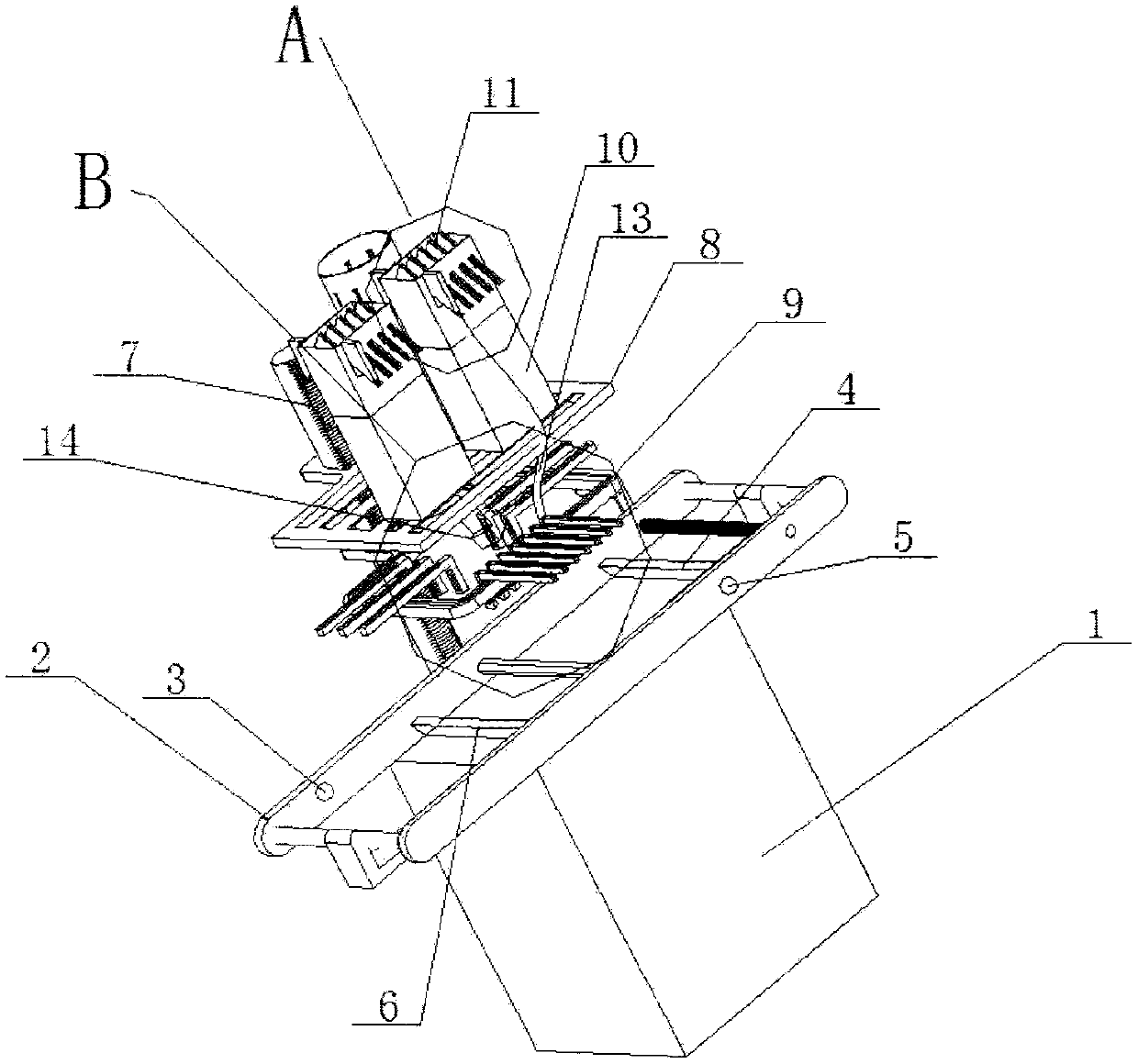
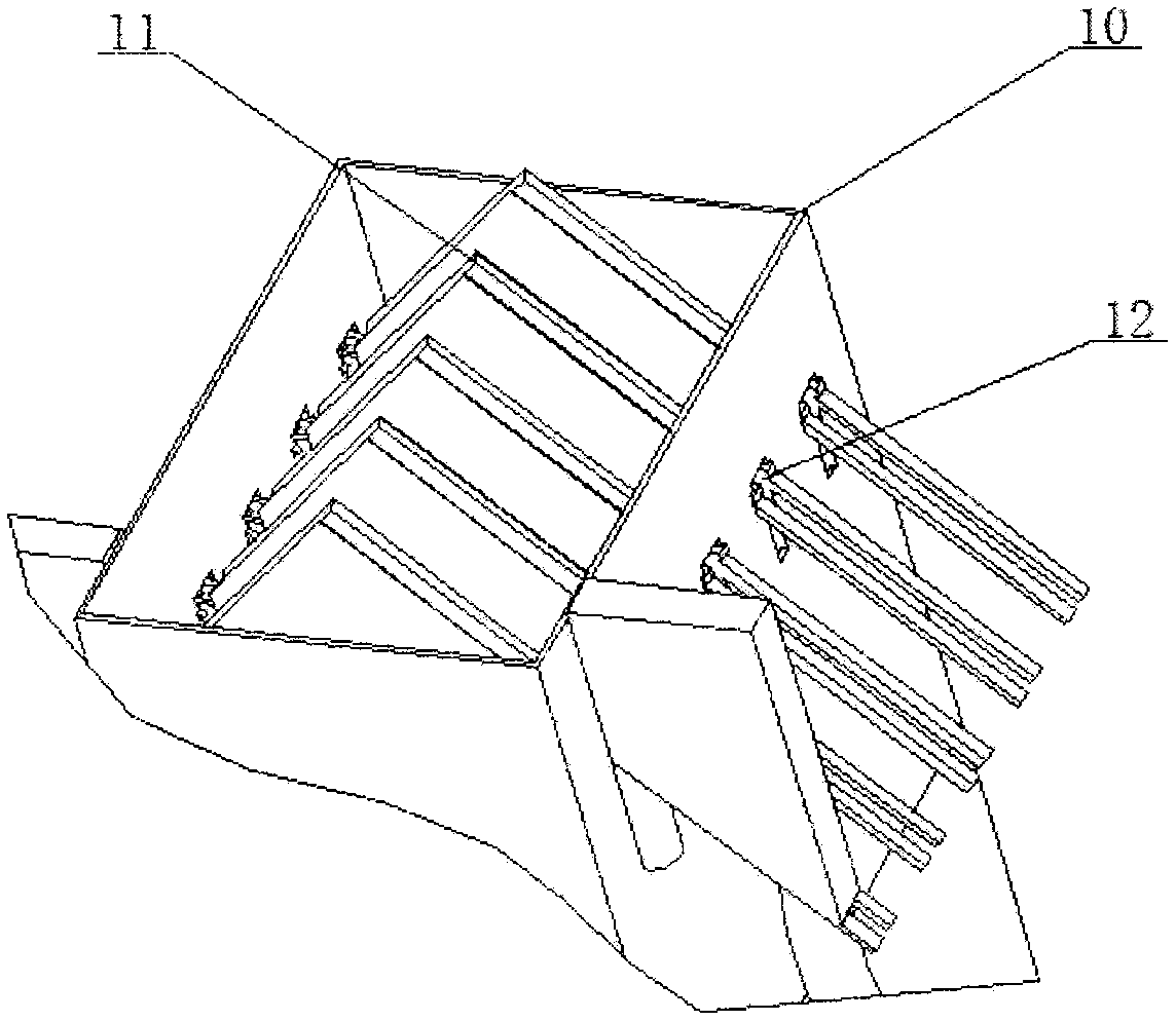
[0029] Such as figure 1 , figure 2 with image 3 As shown, the self-releasing rivet machine includes a base bracket 1, and a conveyor belt 2 is fixedly connected to the base bracket 1. The head end of the conveyor belt 2 is provided with a first sensor 3, and the first sensor 3 is connected to a first baffle 4. The first The baffle plate 4 is connected with a second sensor 5, the second sensor 5 is fixedly connected to the conveyor belt 2, the second sensor 2 is connected with a second baffle plate 6, and the second baffle plate 6 is placed at the head end of the conveyor belt and the first baffle plate 4 between, and the first baffle 4 and the second baffle 6 can move back and forth along the conveyor belt 1, the first baffle 4 and the second baffle 6 can move up and down; one side of the base support 1 is fixedly connected with a pillar 7. The pillar 7 is fixed with an arrangement fixing frame 8 and a rivet collection device in turn from top to bottom. Both the arrangemen...

Embodiment 2

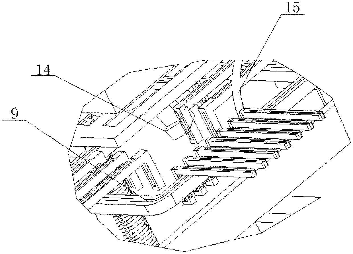
[0032] Such as figure 2 with Figure 4 As shown, the self-releasing rivet machine includes a base bracket 1, and a conveyor belt 2 is fixedly connected to the base bracket 1. The head end of the conveyor belt 2 is provided with a first sensor 3, and the first sensor 3 is connected to a first baffle 4. The first The baffle plate 4 is connected with a second sensor 5, the second sensor 5 is fixedly connected to the conveyor belt 2, the second sensor 2 is connected with a second baffle plate 6, and the second baffle plate 6 is placed at the head end of the conveyor belt and the first baffle plate 4 between, and the first baffle 4 and the second baffle 6 can move back and forth along the conveyor belt 1, the first baffle 4 and the second baffle 6 can move up and down, and the outside of the conveyor belt is fixedly connected with a positioning device 9, The top of the positioning device 9 is provided with a rivet placement device 14, and the rivet placement device 14 can realize...


PUM


Abstract

The invention discloses an automatic-release riveting machine. The automatic-release riveting machine comprises a base support and a rivet collecting device, wherein a conveyor belt is fixedly connected to the base support, a supporting column is fixedly connected to one side of the base support, arrangement fixing frames are fixedly connected to the support and arranged over the conveyor belt, a plurality of rivet arrangement devices are fixedly connected to the arrangement fixing frames, a conveying device is arranged on the rivet arrangement devices, one end of the rivet collecting device is fixedly connected to the supporting column, a positioning device is arranged on the rivet collecting device, and the bottom end of the conveying device extends to the positioning device; due to combined use of the rivet arrangement devices, the conveying device and the positioning device, rivets can be automatically picked up, conveyed and positioned, automatic production is achieved, it is guaranteed that the rivets can be automatically arranged and placed, production time is saved, workloads of workers are relieved, and production efficiency is improved.

Description

technical field [0001] The invention relates to the field of metal stamping, in particular to a self-releasing rivet machine. Background technique [0002] In the field of metal stamping, rivets are relatively common. In the operation process for rivets, manual operations are generally used. This process seriously wastes the production time of the enterprise and increases the work of the staff. Burden hinders the improvement of production efficiency. Contents of the invention [0003] In order to solve the above technical problems, the present invention proposes a self-releasing rivet machine to achieve the goals of saving production time of the enterprise, reducing the workload of the staff and improving production efficiency. [0004] To achieve the above object, the technical scheme of the present invention is as follows: [0005] The self-loading rivet machine includes a base bracket and a rivet collection device. The base bracket is fixedly connected with a conveyor...

Claims


Application Information

Patent Timeline
Patent Type & Authority Applications(China)
IPC IPC(8): B21J15/32
Inventor 莲海
Owner 莲海
Why Eureka
Try Eureka