Continuous riding method and continuous riding device for electric vehicle or motorcycle with punctured tires
A technology for motorcycles and electric vehicles, applied to vehicle parts, tire parts, transportation and packaging, etc., can solve problems such as continuous riding of vehicles, improve the firmness of the overall structure, safety and reliability, and prevent re-explosion Tired tires, cleverly conceived effects
- Summary
- Abstract
- Description
- Claims
- Application Information
AI Technical Summary
Problems solved by technology
Method used
Image
Examples
Embodiment 1
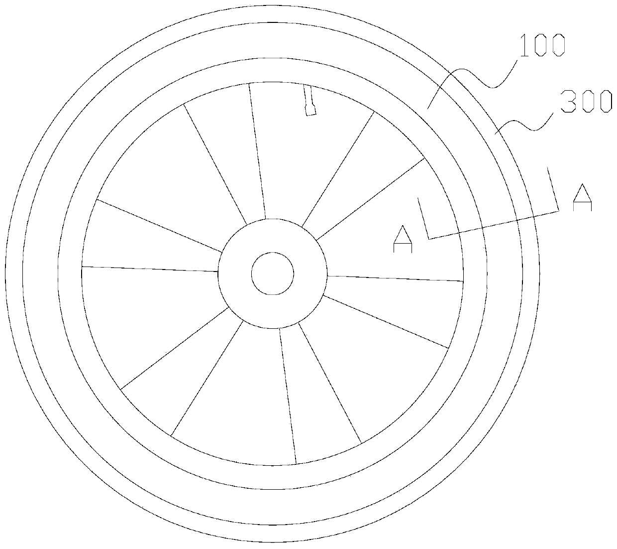
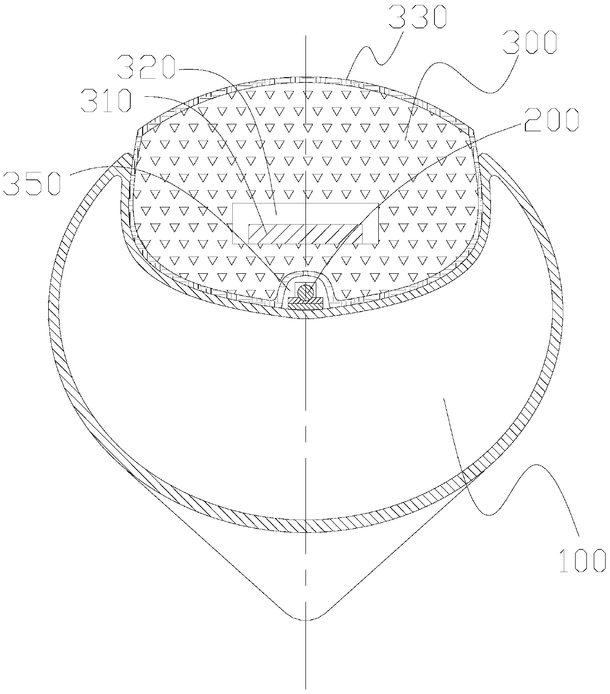
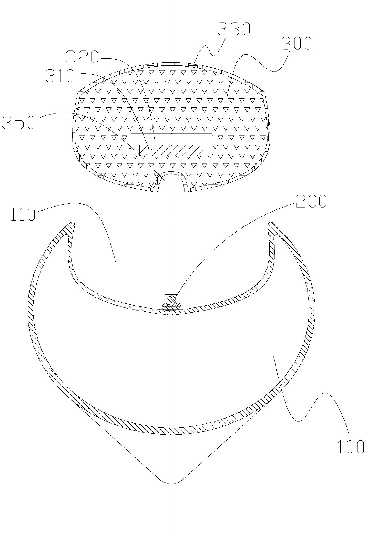
[0041] As shown in the figure, this embodiment proposes a device for continuing to ride an electric vehicle or motorcycle after a puncture and puncture, which includes four belts for hooping the tire 100 after a puncture and puncture to form an annular groove 110 Shaped hoop 200 and a rubber strip 300 used for fixing and sheathing on the annular groove.
[0042] Such as Figure 5 As shown, each strap hoop 200 of this embodiment has a tightening adjustment member 210 and a strip-shaped belt body 220, the tightening adjustment member 210 is fixedly arranged on one end of the belt body 220, and the belt body 220 The other end is provided with a locking hole 230 for matching with the tightening adjustment member, such as Image 6 As shown, four band-shaped hoops 200 are connected in series in sequence, and can be placed on the middle part of the tire 100 circumference side for such Figure 7 The end-to-end enclosing hoop shown in the figure is evenly adjusted and fixed by the ti...
Embodiment 2
[0050] The present embodiment proposes a method for continuing to ride after an electric vehicle or motorcycle has a punctured tire, which includes the following steps:
[0051] Step A, hooping the tire: on the tire 100 of the electric vehicle or motorcycle with a punctured tire, adopt a length-adjustable belt-shaped hoop 200 to be set on the middle part of the circumference side of the tire 100, and shrink the belt-shaped hoop 200 to tighten the tire 100, such as image 3 As shown, an annular groove 110 is formed by hooping the depression in the middle of the peripheral side of the tire 100 .
[0052] Step B, binding the rubber strips: using a rubber strip 300 to set along the annular groove 110, and docking and fixing the two ends of the rubber strip 300 so that the rubber strip 300 forms a closed rubber ring, as figure 1 with image 3 As shown, the fixing sleeve is disposed on the annular groove 110 .
[0053] Exemplarily, this embodiment adopts 4 such as Figure 5 The ...
PUM
 Abstract
Description
Claims
Application Information
 - R&D
- Intellectual Property
- Life Sciences
- Materials
- Tech Scout
- Unparalleled Data Quality
- Higher Quality Content
- 60% Fewer Hallucinations
Browse by: Latest US Patents, China's latest patents, Technical Efficacy Thesaurus, Application Domain, Technology Topic, Popular Technical Reports.
© 2025 PatSnap. All rights reserved.Legal|Privacy policy|Modern Slavery Act Transparency Statement|Sitemap|About US| Contact US: help@patsnap.com


