
Displacement adjustment device for separating knife on spinning preparation machine and its application method

A technology for regulating devices and separating knives, which is applied in the direction of deburring devices, textiles and papermaking, fiber cleaning machines, etc., and can solve the problems of complex structures of fixing elements 19 and discharge chambers 18, affecting the effects of impurity removal and exhaust, and increasing frictional resistance. Large and other problems, to achieve the effect of simple structure, light displacement adjustment, and small frictional resistance

Active Publication Date: 2019-01-25
SAURER CHANGZHOU TEXTILE MACHINERY CO LTD
View PDF1 Cites 0 Cited by
  • Summary
  • Abstract
  • Description
  • Claims
  • Application Information

AI Technical Summary

Problems solved by technology

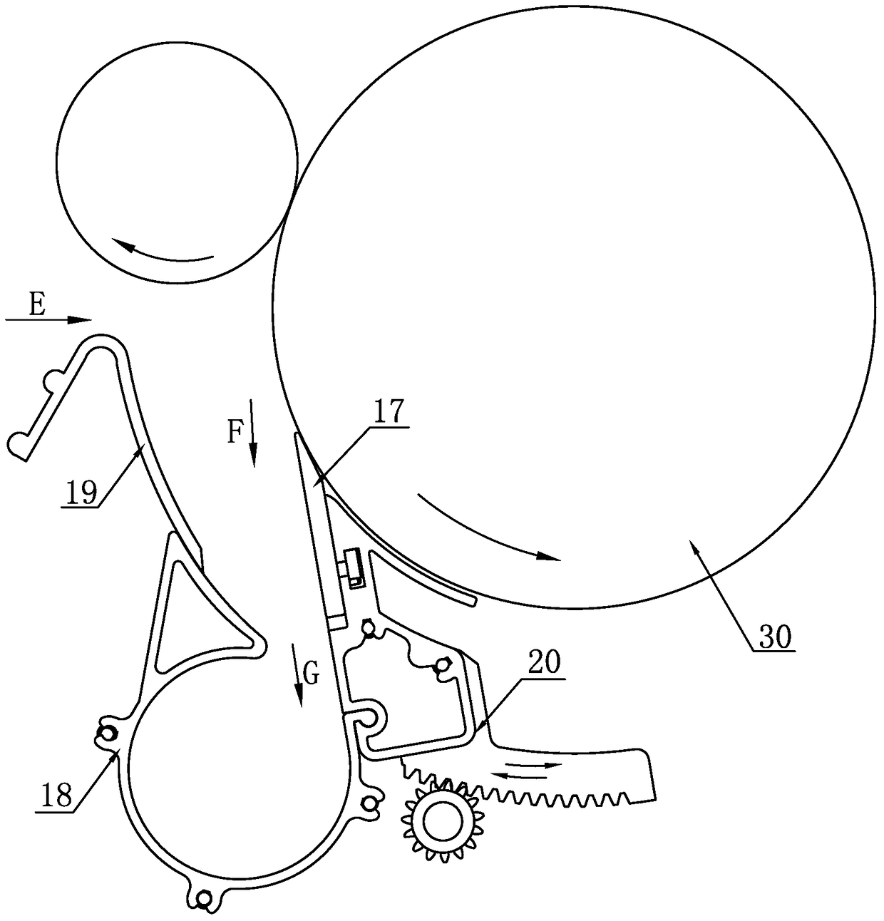
[0003] ① Although this structure can adjust the separation knife to move circumferentially along the corresponding roller to adjust the distance between the separation knife 17 and the fiber separation point, it can guide the separated impurities F and / or air E to the opening of the discharge chamber 18 In G, however, the track between the discharge chamber 18 and the fixed element 19 can be formed by the cooperation of the arc surface to facilitate the inflow of impurities and or air, but there must be a gap between the two, if the gap is too small, the movement between the two The friction resistance increases, and in serious cases, it will cause jamming. If the gap is too large and not sealed, it will cause air leakage, which will affect the effect of impurity removal and exhaust.
[0004] ② The structures of the fixing element 19 and the discharge chamber 18 are complicated, the manufacturing precision is high, the difficulty is high, the cost is high, and the maintenance is difficult

Method used


Image

  • Displacement adjustment device for separating knife on spinning preparation machine and its application method
  • Displacement adjustment device for separating knife on spinning preparation machine and its application method
  • Displacement adjustment device for separating knife on spinning preparation machine and its application method

Examples


Embodiment 1

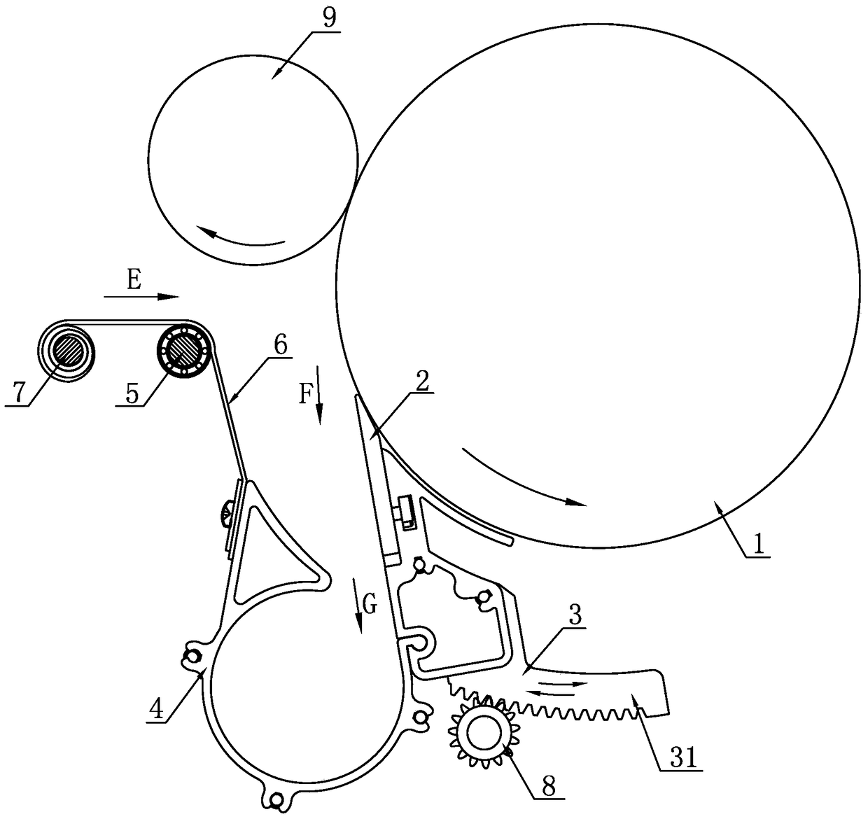
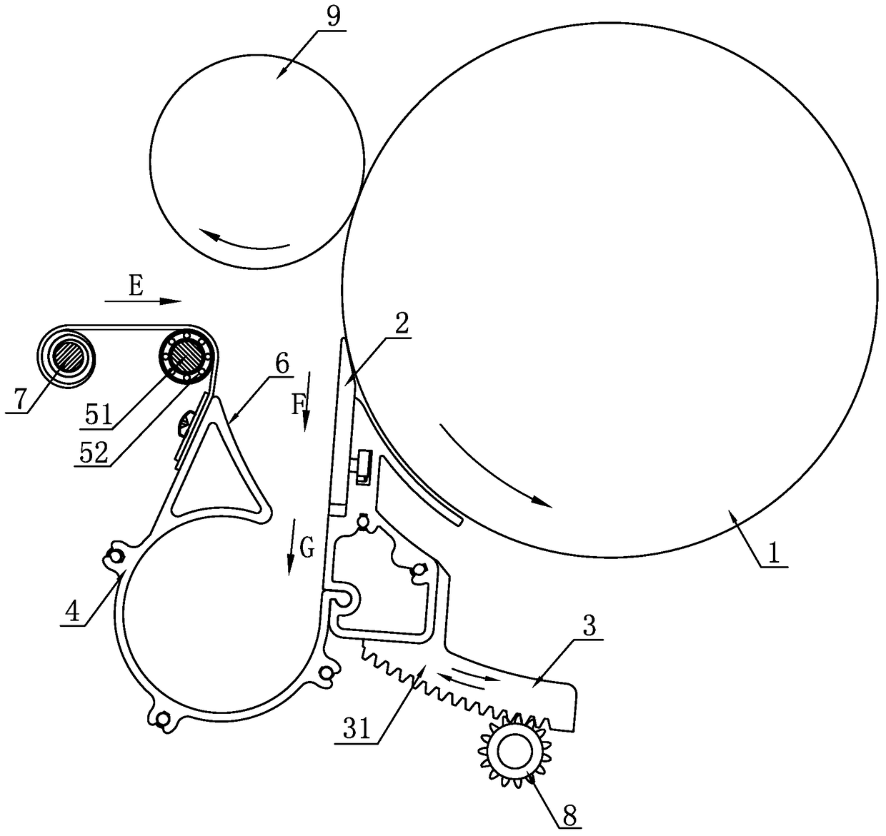
[0020] Embodiment 1: A separation knife displacement adjustment device on a spinning preparation machine, including a separation roller 1, a separation knife body 2, a rotating knife holder 3, a dust receiving cylinder 4, a rolling shaft 5, a winding plate 6, an automatic winding Rolling mechanism 7 and adjusting gear 8, separating cutter body 2 is installed on the rotating knife rest 3, and this rotating knife rest 3 can move along the circumference of separation roller 1, is provided with ring gear 31 at the lower end of rotating knife rest 3, and adjusting gear 8 It meshes with the ring gear 31 on the rotating tool holder 3, the tip of the separating knife body 2 is tangent to the outer circumference of the separating roller 1, the dust-collecting cylinder 4 is installed on the rotating tool holder 3, and one end of the winding plate 6 is fixed At the opening end of the dust receiving cylinder 4, one end of the winding plate 6 is connected with the automatic winding mechanis...


PUM


Abstract

The invention discloses a separation knife position change adjusting device of a spinning preparation machine and a use method thereof. The separation knife position change adjusting device comprises a separation roll, a separation knife body, a rotating knife rest, a dust receiving barrel, a rolling shaft, a rolling plate and an automatic rolling mechanism, wherein the separation knife body is mounted on the rotating knife rest which can move along the periphery of the separation roll; the knife tip of the separation knife body is tangent with the excircle of the separation roll; the dust receiving barrel is mounted on the rotating knife rest; one end of the rolling plate is fixed to the opening end of the dust receiving barrel; one end of the rolling late is connected with the automatic rolling mechanism; the rolling shaft is arranged between the dust receiving barrel and the rolling mechanism and is in contact with the outer side face of the rolling plate. Compared with the prior art, the separation knife position change adjusting device has the advantages that the structure is simpler, the friction resistance is small, the sealing performance is good, the separation knife position change adjustment is convenient, the use is reliable, the effect is good, the cost is low, and the maintenance is convenient.

Description

Technical field: [0001] The present invention relates to spinning preparation equipment, for example, carding machine, blowing machine, opening and dedusting machine or similar machinery, especially relates to the separating knife displacement adjustment device therein. Background technique: [0002] Federal Germany's Trufischer Co., Ltd. and KGG disclosed a "device with at least one separating knife on the spinning preparation machine" in the patent No. 03142594.1, and its core technical solution is: the separating knife wherein 17 is installed on a support member 20, and this support member 20 can move parallel to the circumference of described roller 30, to adjust the distance between separating knife 17 and described fixed position relatively fixed element 19, is installed on support member 20 A discharge chamber 18, which cooperates with a first arc-shaped leading edge fixed on the fixed element 19, which is arranged to be in a fixed position during operation of the mac...

Claims


Application Information

Patent Timeline
Patent Type & Authority Patents(China)
IPC IPC(8): D01G15/34D01G9/14
Inventor 朱中华许小平王刚张永平
Owner SAURER CHANGZHOU TEXTILE MACHINERY CO LTD
Learn More